Near the end of the lifecycle of mass-market commercial product development, an engineering team may come in and make a design for manufacturability (DFM) pass. The goal is to make the device easy, cheap, and reliable to build and actually improve reliability at the same time. We hackers don’t usually take this last step, because when you’re producing just a couple of any given device, it hardly makes sense. But when you release an open-source hardware design to the world, if a lot of people re-build your widget, it might be worth it to consider DFM, or at least a hardware hacker’s version of DFM.
If you want people to make their own versions of your project, make it easy and cheap for them to do so and don’t forget to also make it hackable. This isn’t the same as industrial DFM: rather than designing for 100,000s of boards to be put together by robot assembly machines, you are designing for an audience of penny-pinching hackers, each building your project only once. But thinking about how buildable your design is will still be worthwhile.
In this article, I’m going to touch on a couple of Design for Hackers (DFH) best practices. I really want to hear your experience and desires in the comments. What would you like to see in someone else’s open designs? What drives you nuts when replicating a project? What tricks do you know to make a project easily and cheaply buildable by the average hacker?
Design for DIY
Your audience isn’t technologically illiterate, but they’re not pick-and-place machines with micrometer positioning accuracy either. You want to make the assembly easy on them, but you don’t want to have to use through-hole components that are as big as your head and becoming more and more difficult to source all the time. What to do?
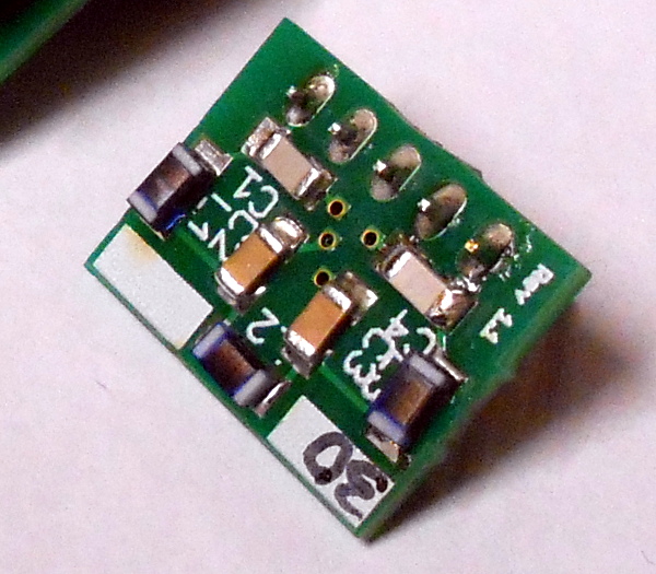
That’s not a rhetorical question. What should we do? I’m entirely happy soldering surface mount technology (SMT) down to 0805 and 0.5 mm pin-pitch with good illumination and a magnifying lens, but below that it gets tricky. People who use solder paste and reflow can handle even smaller parts. But if you require reflow skills to rebuild your project, you’re also limiting the potential audience to a small percentage of Hackaday readers, much less the entire human population.
Home etching is doable down to just about the same resolution as hand-soldering in my experience, but only with a bit of practice. Double-sided boards can be made to work at this scale with yet more practice. When your design gets complicated in these directions, you force the hacker to outsource the PCB fabrication. These days, that’s less and less of a problem, but depending on where people live it can introduce a delay even if it doesn’t add much extra cost to the project.
 But if you want people to copy your design, think about the difficulty of DIY manufacture versus the gains you get from using a given technology. There are definitely discrete jumps of difficulty. Almost nobody is making four-layer PCBs at home, and relatively few are making double-sided boards. Once you need to move beyond a single-sided board with a few jumpers, you can pretty safely go nuts on the complexity of a professionally fabricated PCB, which means that you can also use tiny little track widths if you need to.
My best guess is that 1206, 0805, and the bigger SOIC parts are not show-stoppers for the average Hackaday reader even with the most brutal soldering iron, but I could be totally wrong. What’s your tolerance for bigger SMT parts? How many through-hole holdouts do we have out there?
Design for Modules
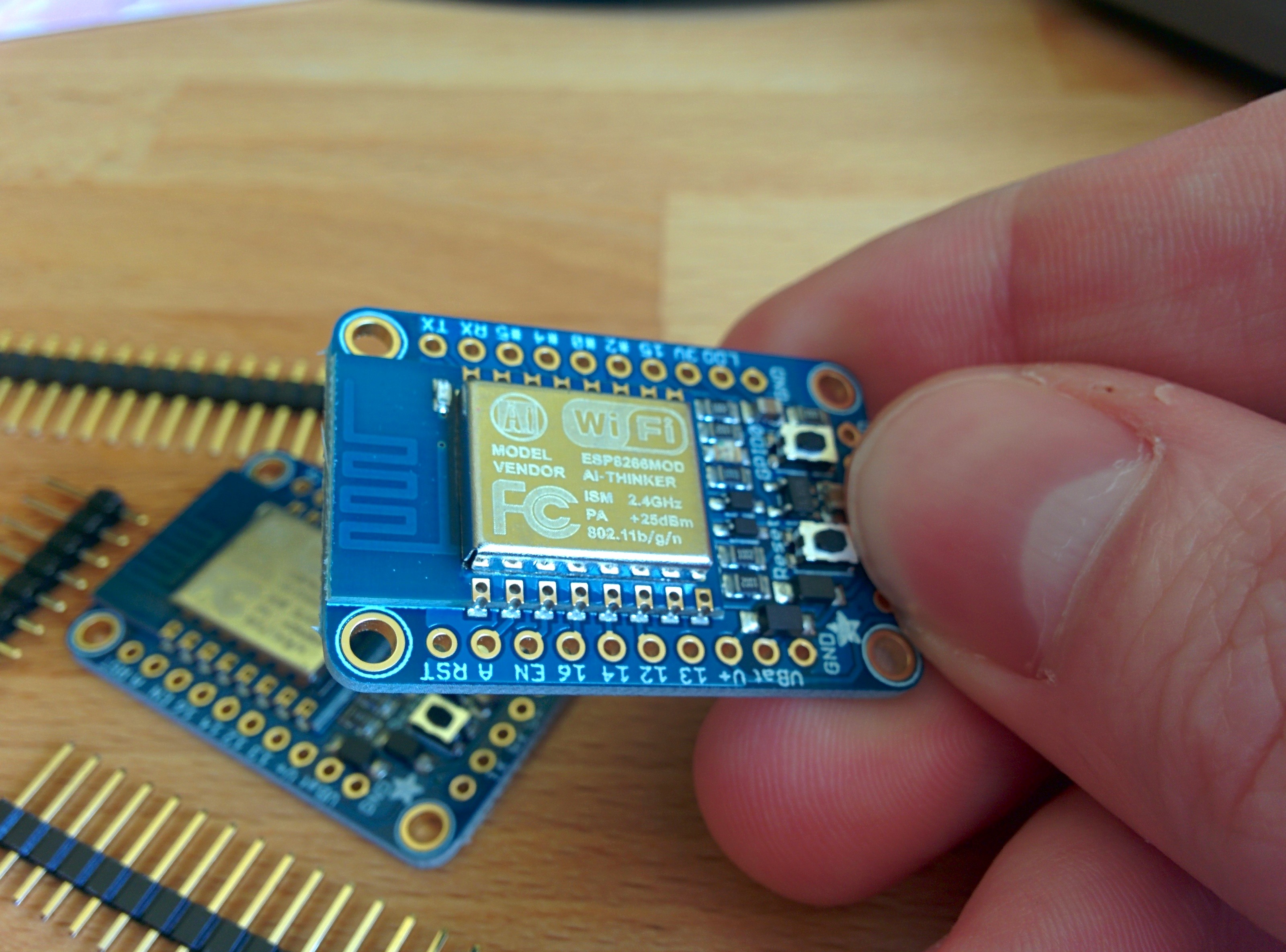
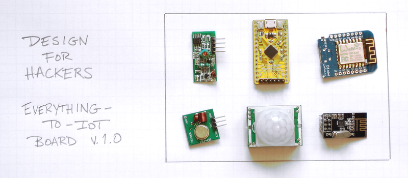
There are some cases where you can’t avoid tiny parts, or where the fabrication of the board itself really matters. In these cases, using already-built DIP modules can often help. This is fairly obvious for things like radio-frequency parts: high-frequency circuitry can be tricky so having a tested design for the radio part guarantees that it will work. As long as you’re not making a custom radio, designing in a module like an RFM69 for ISM bands, nRF24 for 2.4 GHz, an HC-05 for Bluetooth LE, or an ESP8266 for WiFi is probably the only reasonable choice in single units. They (and similar radio modules) are an amazing bargain considering the development time and effort they embody.
The same goes for wired connections. Things like the ENC28J60 Ethernet LAN module, and USB-serial adapters are also available about as cheaply in module format as the individual parts would be in small volumes. This is the economics of scale: I can buy a complete ENC28J60 module for less money than I can buy the chip, magnetics, and a crystal to run it. It’s no surprise that we see more designs incorporating these modules whole, versus re-building them from scratch.
CPU Modules
The surprising exception to this rule is in the choice of microcontrollers. I’ll be the first to admit that I have a stable of favorite microcontrollers that I draw from depending on the features that I need — one that I like for its DAC, another that I like because it is fast, another because it has many SPI peripherals or USB and so on. I’ll buy these in sticks of 25 or so, where they’re cheap. I’ll make 25 projects eventually, or end up with half-full sticks cluttering up my closet.
For a one-off project, all of this is over-optimization and a waste of time, effort, and money. And if you want another hacker to reproduce your project, what matters is the single-piece cost and the ease of incorporating the microcontroller into the design. The design-for-hackers alternative is to settle on one of a couple of cheap microcontroller modules.
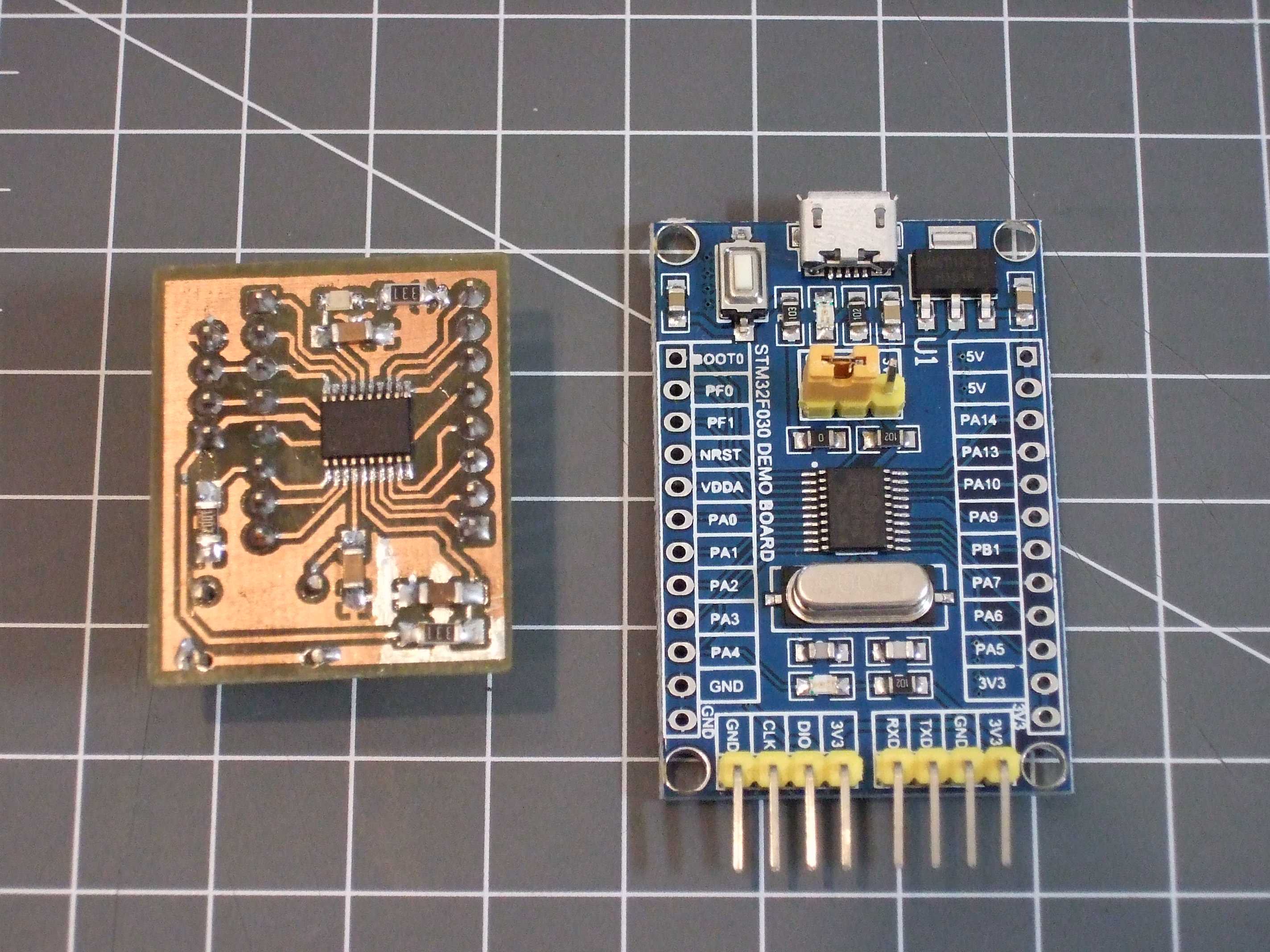
Everyone with access to eBay can get their hands on a pre-soldered ATmega328p or STM32F103 board with a crystal, power supply, and all of the pins broken out for just about the single-source cost of the microcontrollers themselves. There are, of course, a wide variety of modules out there, but the ubiquitous “Pro Mini” and “Nano” Arduino knockoffs and the Maple-mini clones shaped like a blue stick (search for “STM32F103C8T6”) are obvious choices from a price/performance perspective.
These modules, just like the RF or Ethernet modules, take a lot of the soldering and assembly work off the hacker reproducing the project in single-unit quantities. It’s a win all around. In my opinion, any project that specs an ATmega or STM32F10x chip by itself, rather than in the eBay-friendly module format, is doing the hacker a disservice.
The Cost of Modules
The downside of using modules is that you’re at the whim of the market. You can buy complete nine degree-of-freedom IMUs today for prices that were unheard of five years ago, even for the raw chips in quantity. But you don’t get your choice of IMU. You have to buy the most popular one, so there’s a design constraint.
The particular STM32 chip in the Maple Mini knock-offs is fairly old, and its peripheral set is limited relative to the entire lineup. It lacks the DAC of its newer brothers, for instance. But for the price of an outboard DAC and some SPI hookup, you can get both better output quality and reduce the soldering complexity for the DIY’er. That’s a win in my book.
The other, hidden, cost is that some of these modules can be flaky. I’ve personally received one bad STM32F103 “blue pill” board out of an order of five. Bad luck? Probably. But I’ll test the chips out before I solder them to my main board from now on. The upside of the pre-built module format is that this is very easy to do because it’s got all the programming and power pins already built in.
Conclusion
I’ve just scratched the surface of Design for Hackers, but the column’s already long enough. Next time, I’ll look into things like layout considerations, parts selection, and tricks to reduce BOM cost for single-unit manufacturing. Heck, maybe I’ll even begin to practice what I preach.
Until then, please leave your comments on your experience with (SMT) part sizes, board layering, and module use in other peoples’ projects. Include links to particularly good examples of best practices. What little touches have made your life easier? What design choices work for 100,000 quantities, but fail when translated to the DIY lab?


“The other, hidden, cost is that some of these modules can be flaky. I’ve personally received one bad STM32F103 “blue pill” board out of an order of five. Bad luck? ”
No, i think it is common. I have experienced defective or very bad quality devices when buying in multiples. Even wrote some complains about this stuff here http://www.electrobob.com/cheap-china/
Also, a lot of this stuff is not lasting as long as they should.
I’ve bought tens of those STM32 boards – I seem to have had a much lower failure rate, but the failures I’ve seen are all poor soldering jobs. On one particular bad run, a few boards were outright missing ICs, and when there have been failures, I’ve traced every single one to a poor solder joint or short in the reflow job (and they were usually pretty obvious)
Actually read through the list, I’ve been very curious to figure out if those CP2102s from China are counterfeit. For me they’ve worked extremely well in all my stress testing (random bursts of data at up to 1MBaud, and I’ve tested 100s of MB of data exchanging between two CP2102s so far). I read through the datasheet about the serial number – apparently Silabs does not program unique into the CP2102 (the datasheet says each one is programmed with a default of “0001” and it’s the end user’s job to figure it out). I actually suspect the Chinese CP2102s may all be genuine, and Silabs just prices the ICs so cheaply in China that no one bothers to clone their IC.
Hm… you made me curious about the CP. I will check the datasheet and programming options, maybe I missed that part. Yes, indeed I have generally good experience with them as well.
You are also right about the solder issues, for some things it is obvious, but for others not. I do have to admit to dropping the device and moving on to the next one quite quickly actually.
I bought four small L298 dual DC motor driver boards for a project a few weeks ago and one of them had a pin un-soldered on one of the screw terminals. This was weird because it was a through-hole part and the rest of the soldering looked too even to be done by hand. Worked fine once I soldered it, though.
FWIW I’d argue that one of the most important things to include is decent documentation, in both the hardware/electrical realm as well as any associated software. There’s no end to projects/boards that work relatively well with the exact set-up the original person envisioned, but as soon as you move outside of that region I find I’m either blindly hoping for the best (which doesn’t always end well), or have to spend a lot of time poring over a schematic or undocumented source code (which loses its charm quickly)…
I do have a few projects here; http://www.rabidmantis.se/ where I’ve made an effort to document at least some parts of them. I haven’t really added anything new recently, but the projects there may either be useful in themselves or as a starting point for others to document their projects as well =)
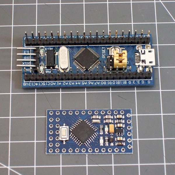
Oh my god, that photo of the Pro Mini, what did they do to the design? Sorted all components by size and used autorouting? Too much tetris? Better steer clear from those, and get ones that look more like the original one.
Meh. The nice thing about this pro-mini design is that they actually managed to squeeze a 6-pin ISP header in there so you can program the chip directly. It’s a little too close to the switch, though, and fits a bit wonky on the top of the board, but it’s much better for my purposes than the ones that don’t have the 6 pins broken out. Fat pogo pins, and you’re in business.
This design is optimized within a millimeter of its life for board space, though, and it’s on a thin (cheaper?) PCB. It’s definitely not deluxe. But all-up, with pin headers and postage, it’s cheaper than a bare ATmega328p from Mouser. Tradeoffs.
That’s not what I meant. There are cheap clones out there that don’t look like they are re-done by a 9yo:
http://g02.a.alicdn.com/kf/HTB1qdwkJVXXXXb0XVXXq6xXFXXXU/ATMEGA328P-Pro-Mini-328-Mini-ATMEGA328-5V-16MHzwith-Pin-Header-for-arduino.jpg
And of course lack of 6-pin header doesn’t preclude programming directly — you connect your programmer to the SPI pins exactly the same way, they are all broken out. Sure, you have to use dupont cables instead of pluggin the programmer directly, but I’d use cables anyways for convenience.
The older pro mini clones (with 2 rows of pin-holes on the back end) Break out the SPI which is useful not only for programming, but also for hooking up to a SD card. They also break out all 8 analog input lines. The new ones (pictured above by daasheep) do not, including the D4 and D5 pins which also function as SDA and SCL. Soooo, on the new ones, there is no place to hook up I2C. Epic Fail!
Look closer, there are both A4/A5 and A6/A7. I use I2C a lot with those boards, too.
My three main project milestones:
1. DFF (Design for Function/Form/Features)
2. DFC (Design for Compliance)
3. DFM (Design for Manufacturing)
No praticular order, i jump between these tasks until all these milestones can be completed with one single solution.
Something a lot of hackers/diyers seem to forget is test points. It’s pretty much mandatory to have them for in circuit testing and programming in series production. In the prototyping stage these testpoints can actually be very handy, makes it easyer to find errors and hack fixes on a board if the signals are accessible on adefined spot. If your project is intended to be (ab)used by hackers too, i would actually go as far as to put as much of the unused IOs of ICs/µCs on a testpoint somewhere, maybe someone wants to make simple change, and soldering wires to 0.5mm pitched QFN or even QFN packages seems to be reserved for experienced/advanced soldering iron operators.
Good call. I was going to do PCB design tips/tricks for next session.
I go back and forth about which pins to break out to test points. A lot of my stuff uses serial with AVRs and the programming/debugging pins on ARMs, so those are a must. Power pins are good too.
Things like SPI lines can be spied on by clipping on to the chips that they use, though, so I don’t often test-point them. But then I’m not doing large volumes.
DFT (Design for Test): Pretty much the usual test pads. The test pads are limited by the tester. JTAG chains for connectivity between high I/O count digital parts, BIST for exercising the processor and memory; Analog/digital Loopback.
Are there any specific standards here? I’ve heard jigs have to be made for most pogo pin test point designs, but is there a way to generalize the jig layouts?
I don’t think there are standards for test jigs. At least i’m not aware of them, but sometimes the IPC jungle can be a bit too thick to see every tree in there. I am CID+, but still, i only know a piece of the standards i use in my daily work. Test jigs get designed at our production facility, and they only give us designers some rough guidelines as to how we should layout the testpoints (pad size, minimal pad-pitch, guide- and mounting holes,…)
Even if you don’t need or plan on using a test fixture, JTAG, etc. on your project, put in some ground test points along with every supply voltage present. One on every clock oscillator is good too. If the user has problems the grounds will make hooking up a scope much easier. As for power and clocks, a very large number of problems can be traced issues with those.
Number of Part to Solder. For example, there caps in special packages that cost more but have the specs to replace 2 regular caps.
Keep it Minimal, if possible. Everybody wants something else. A board with core functionality with addons is optimal, if possible.
Use open source or at least free design tools. No eagle.
Use 1.27 mm pitch more often, but stay away from 2.0mm. So if 2.54mm is too big, don’t use 2mm!
Oh yes, those 2mm headers pissed me off a lot of times!
It might be worth mentioning Design for Disassembly: Are the parts easily reclaimed for recycling when you’re through playing with it?
You may want to also consider Design for Disassembly: Big in the auto manufacturing, it applies at this level too: can you reclaim/recycle the parts when you’re through with it?
Interesting idea. Besides sometimes socketing modules / LCDs / etc, I’ve never thought about that. It’s probably not worth doing for anything but fancy parts, though, right?
How do you disassemble SOICs and other SMT devices?
You can get SOICs off with Chip Quick, but the modules are another approach – use recepticals instead of hard soldering them to the board, and you can pop your modules off and reuse then in the next project.
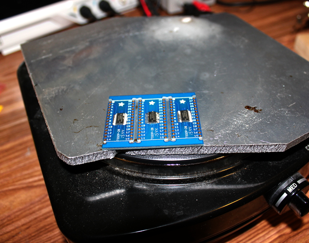
SMT are pretty easy to remove and far more reusable than through hole parts. You can do so with a heat gun or just throw the whole board into a $20 toaster oven and shake off the parts.
To add to this: you can try to minimize the types of parts used within your projects, which makes it more likely to reuse stuff.
“My best guess is that 1206, 0805, and the bigger SOIC parts are not show-stoppers for the average Hackaday reader even with the most brutal soldering iron”
In my basement lab…
0603 and parts with accessible pins (even fine pitch TQFP) are not a problem with a soldering iron and vision assistance (well, needed for my aging eyes). 0603s are my jelly bean part size of choice.
0402 and fine pitch QFN even with hidden pads are no problem if I purchase a small steel stencil and perform toaster oven reflow magic.
With so many options for inexpensive professional PCB fabrication, unless you absolutely need a PCB -today-, it may not be worth worrying about design for basement PCB fabrication.
I agree that designing with well established, or well copied, modules is definitely a way to get some extra bang for your buck.
A agree with @Lars R. and add:
Publish data for manufacturing and good reading (scheme in pdf, gerber files, …).
Keep in mind size of parts….if you have a huge thd cap close to small smd part, sometimes is not possible to solder it by solder iron.
Some smd parts have “power pad” for better cooling and good practice for diy solder is to design large enough vias for easy soldering.
Really agree with PDF for schematics. Nothing frustrates me more than going to the documentation only to find the schematic is in some obscure CAD format.
My big issue with replicating a lot of open-source stuff is just sourcing components. A surprising number of projects don’t bother creating a bill of materials at all, and those that do often source from 50 different suppliers to get the price as low as humanly possible.
Screw that. I don’t want to read a 600-page forum thread to track down all the details, I want a big list of every single thing I have to buy. And I’ll gladly spend an extra $10 to get all the parts from 2-3 sources instead of placing orders from a dozen suppliers all over the world, half of whom are usually out of stock.
Sourcing and BOM: I’ve been guilty of that one, and that’s going to be in the next installment.
TLDR: just b/c _you_ (read I) have a fantastically stocked junk box with surplus-electronics parts dating back to the 1990s, does not make the parts “available”.
I agree with you, mostly by looking at the part collection that I have. I tend to use what is available over buying new things. But the things I have available could have been sourced from different places at different times. I think this applies a lot for hobby / small batch.
I propose Design For Reality (DFR). There are Soooo many “Maker” projects out there from the 1st-World that DO NOT understand that here in the developing world are essentially “Unobtainium”. Where possible in projects that I intend to be possibly replicated by 90% of the people on Earth, I design with loose constraints using very easy to find components. Even this approach is difficult because Chinese fakes are prolific in the third world, and often deviate from legitimate manufacturer specifications.
Perhaps it would be best to not only add a Design for Hackable (DFH) moniker, but (where appropriate) add a Design for Reality (DFR) qualifier.
Regards, David in Jakarta
So now we have to design for someone making $18k or less a year?
It should work with Chinese fakes?
It should have geographical BOM variants so everyone can find large piles of parts in neck of the woods too?
I’m going to say DFR should be specifically reserved for anything you couldn’t build. “Developing world” my ass.
My country just sucks slightly less than yours. Would love to see your designs though…..
@First world “A**Hole” (there’s really no need for using foul language)…
So now we have to design for someone making $18k or less a year?
Answer: YES at the Global “Maker” level.
It should work with Chinese fakes?
Answer: Generally YES. I know this is difficult (from personal experience), but this requirement is a DFR goal.
It should have geographical BOM variants so everyone can find large piles of parts in neck of the woods too?
Answer: NO, only part numbers (or hopefully suggested commonly available “close” equivalents). That’s the point of DFR in the “Third-World”.
I’m going to say DFR should be specifically reserved for anything you couldn’t build. “Developing world” my ass.
Answer: I don’t completely understand your point on this reply from you. DFR should be something that is “tolerant” of part performance differences and/or availability in the developing world. As I stated, we’re talking about simple but very instructive designs for learners at the “Maker” level. If in Indonesia, for example I might be able to get a “working” example of an LM386 OpAmp, a PN2222 transistor that’s not quite up to snuff (likely a Chinese fake), or an LM317 legacy regulator that just doesn’t cut it at the edge of a legitimate data-sheet spec. But it will work – within reason. The DFR concept is Design for Tolerance at a basic tutorial level, especially in the developing world.
My country just sucks slightly less than yours. Would love to see your designs though…..
Answer: I don’t know what country you live in, but I’ve lived all over the world, and understand the problem with fakes and tolerance and near impossible access to “real” parts. There are lots of examples of what I’m proposing with DFR, do your homework. There are plenty of examples of “Maker” level yet useful electronic designs from the likes of India, China, and even here in Indonesia where I live currently. These designs use legacy parts with design tolerances I would NEVER employ in a production level design with any level of volume. But that’s what’s available in the developing-world, so you just deal with it!
This mind-set is what I’m proposing to encompass by the Moniker: DFR.
OK?
It can be done, but like a lot of the software project, don’t expect them to optimize something that are more efficient and requires cheaper hardware. I would love to see people release more native C program instead of the hated Java, but that’s not going to happen if the programmers values their time more than the time of the people that use their bloated code. Same is in the hardware world. Want a blinking LED, go get yourself a Arduino with 32K of memory. They don’t care about the most efficient implementation. :P
No one pays for R&D and optimization as there are no direct profit in this game, so it is DIY if you want something that fit “your reality”.
There’s just too many realities! I moved, socioeconomically laterally, from Washington DC to Munich, and couldn’t find a 2904/2906 transistor pair to save my life. There were all these BCxxx thingies? It wasn’t too hard to figure out substitutions in the end, but it’s a barrier, and you still have to be wary of the pinouts.
But @Drone, I see your main point about availability/affordability too. That’s actually part of the reason that I want to push the lowest-common-denominator eBay modules for the higher-tech stuff. China Post ships as fast to Brazil as Germany (and significantly faster to the US).
Does that make parts ordered over eBay a good baseline? (I have very little experience outside of the US, EU, and China.)
Hi Elliot,
Just a quick answer (it is very late my time): There are lots of resources on the Web regarding different transistor and/or diode part number differences from region to region. Wikipedia has some decent pages on this subject with follow-on links, but you have to dig. For-example, depending on your region, there are the likes of the JIS, JEDC, NEMA etc. standards. With a bit more research, you should be able to find Web-based aids in cross-referencing types (isn’t the Internet great?!) Also try the NTE company web site. NTE has what are commonly referred to as “generic” parts that can be cross-referenced by part number. So you might find close if-not equivalents in terms of specifications depending on the NTE part numbers. Matching (withing tolerance for your specific application) is the point when it comes to this method.
As for U.S./EU reputable suppliers vs. ebaY and China direct suppliers: It should be obvious that first-world suppliers can be (generally) trusted. Otherwise, YMMV. And YMMV includes ebaY and/or Alibaba, where anything goes in terms of fakes. But that’s not to say you can’t get low-cost decent if-not tolerable parts inexpensively from these online sources, just keep your expectations in-check.
Where I live currently (in the Third-World), reputable distributors are almost impossible to use. There are HUGE problems with import and (most important) no easy way of online payment. So we have to deal locally, and take what we can be lucky enough to find.
Here’s a kick-off page from Wikipedia with embedded and external links – just a start:
https://en.wikipedia.org/wiki/JEDEC
This idea of DFR is important especially if you’re creating something that there will be alot of interest in; if you’re just developing for yourself, you can do whatever you want. If you outsource the boards and even the manufacture of completed boards, you bridge the availability gap… and at the low cost of this and the complexity and size of modern boards, this is an easier step to take.
Re “workability”, I can do some work with SMT, but aging eyeballs and fingers like bratwursts do not do so well with it, and it’s a big step to tool up for serious SMT work. I have a stockpile of my favourite active devices in DIP and thru-hole. For more modern devices, I usually just look for a popular module or board with it. Saves time and hassle.
Hi Ken N,
My DFR concept is exactly for as you describe, design to be published and reasonably duplicated in the third-world. If you’re doing your own prototyping and do not intend to publish, then there is no need to consider the DFR Moniker.
My experience here in the developing world is that the likes of home-made PCB’s using toner-transfer (or similar) is prolific in the “Maker” community, so that’s not an issue. Blank PCB’s are readily available, but mostly phenolic one or two-sided boards, lesser-so FR4 (but FR4 still available with a bit more searching).. Etching chemicals are store-bought over-the-counter consumer cleaning type products (disposal is NOT environmentally friendly, but the volume is low). Through-hole and reasonable sized SMT home-made boards are prolific, I don’t see any aversion to through-hole vs. SMT here. Hot-air and/or oven solder and/or rework is fairly rare, but there are solutions available locally, but at a cost that is typically not tolerable locally.
Thank you for your reply Ken…
i’ve been soldering for more than 20 years, but i still suck at it. if anything it’s getting harder because my hands shake sometimes. i’m soldering TO-92 without spreading the pins out first, and that is not “easy” for me. so surface mount is kind of a show-stopper for me.
but your advice to use modules is spot on! i swore by PICs in DIP packages for a long time, but i’ve now done two projects with an STM32 discovery board at the center of it, and it is just the most convenient embedded development experience i’ve ever had. the tiny SMT package is entirely mitigated by the big 0.1″ headers on the development board. they’re not quite as cheap as a PIC but close enough for me.
really i have just wanted to say something good about the STM32 :)
the Nucleo-32 boards come in an arduino Nano form factor. Includes an STM32F3/STM32F0 part with a built-in debugger, USB-to-Serial and USB-drive programmer all for about $15. Not quite as cheap as the bluepill, but comes straight from the manufacturer with plenty of documentation and excellent build quality.
The latest Nucleo-32 board is the NUCLEO-L432KC with 256KB Flash, 64KB RAM, 80MHz Cortex-M4 + FPU and a tonne of peripherals. Costs $15 CAD (thats like $11-$12 USD) , and comes with debugger, USB2Seriaal, and USB -drive programmer. all squeezed into a arduino Nano form factor. A great platform for those that don’t like using cheapo boards from China.
http://www.st.com/content/st_com/en/products/evaluation-tools/product-evaluation-tools/mcu-eval-tools/stm32-mcu-eval-tools/stm32-mcu-nucleo/nucleo-l432kc.html
Wow. Thank you for pointing that out
The Nucleo boards, especially for the high-end chips, are a phenomenal bargain. And the programmer that comes with them is first-rate and designed to snap off and be used stand-alone. I’ve been using one as my main ST programmer for the last year — it’s got full flash/debug capabilities as well as a pair of serial lines.
http://jeelabs.org/book/1547a/index.html has a decent tutorial, for instance. I should really buy another and do a step-by-step article for HaD.
The Discovery boards are also great, but their prices are a bit inflated by the (awesome) peripherals they have on board. It’s just rare that you’ll find a project that uses a DAC, ADC, accelerometer, and whatever else they toss onboard. For experimenting with the peripherals, which was their design, they’re perfect.
But yeah. If you’re looking to get started with ST’s ARM chips, the Nucleo series hits it out of the ballpark in price/features/ease of use. Everyone should have at least one.
Nucleo boards are available for quite some time. But what halherta posted is a Nucleo of the size of an Arduino NANO that could fit in a light switch. Also, this one is even cheaper than the standard Nucleo boards.
There was always a lack of small STM32F4 boards. The Chinese never made those. Yes, this one is a STM32L4 with “only” 64KB Ram. But it might run micropython better than ESP8266 and nRF51 (Coming up next: ESP32 and nRF52). Micropython is native to the STM32 architecture, ESP32 and nRF52 are not. Until those are supported, this Nucleo nano is currently the smallest, cheapest, well-supported, powerful 32bit MCU board that I know of.
Yeah, the Nucleo-L432KC board is quite impressive. Being a Nucleo-32 board (as opposed to the standard Nucleo-64 or larger Nucleo-144 board category) the STLinkV2-1 cannot be broken out or used with an external target. But given its size and the peripherals on it (2 DACs, 5MSPSADC and much more) it’s still quite impressive. I checked my local offline mbed setup and it seems to already have mbed suppport when using the latest mbed libs from the github (mbedmicro) offline. I imagine mbed support in the online compiler is incoming. https://developer.mbed.org/platforms/ST-Nucleo-L432KC/
Thanks Lars R. for pointing out that the board could make decent MicroPython candidate
I’ve already ordered a couple from mouser.
I think what makes the ESP8266 a really good candidate for micropython, despite its architecture not being native; is the built-in WiFi. No need to add another chip. All the hardware is already integrated, making using micropython for iot apps simpler and cheaper.
With the advent of the ESP32, having both WiFi and bluetooth, more RAM and more IO will make it n even greater little cost-effective ‘micropython’ machine. Though with the RPi Zero costing $5 and the CHIP costing $9 (both run normal CPython and the CHIP has both builtin WiFi and bluetooth), I’m not really sure how micropython on an ESP8266/ESP32 would be able to offer something/value that isn’t already offered by those low cost platforms.
I’d love to read one that was a getting started guide based on linux as the OS
matt, have a look here:
http://www.openstm32.org/HomePage
You can download an ST supported development environment called the ST SystemWorkbench based on eclipse. Available for free on Windows & Linux (You will need to create an account).
Many Nucleo boards are supported by mbed. You can also create an mbed account and gain free access to an online mbed compiler/ide. If online compilation isn’t you’re thing. haave a look at platformio & platformio-ide. It’s a build system that also supports nucleo boards with mbed libraries offline http://platformio.org/
There’s little need to mess about with makefiles and cli tools in 2016…..unless you’re like me and enjoy doing things old school.
I like the idea of designing PCB boards that can have other modules and breakout boards plugged into it. For example if building a board for a robot, perhaps it can have its own power supply circuitry ‘layed out’ on the board, but then provide sockets for; an Arduino Nano (or Compatible), an SMD Hbridge breakout board, and for sensors e.t.c. The board itself can have some easily solderable components on it; both through hole and SMD, but the crazy stuff can all be added as modules/breakout boards that can be cheaply bought from Aliexpress or ebay.
Let’s face it even those who can solder SMD, are no fans of doing it manually unless if its just a prototype built with the intention of future commercialization. I know I don’t find manually soldering smd components fun at all. And I’ve done quite a bit of it over the years.
Somewhat tongue in cheek, but just barely; “Design for Hackers”? While I admit I may be missing something, but is that an oxymoron? A hacker is celebrated for modifying just about anything to suit their needs or desires, shouldn’t they be able to work with anything not designed for hackers? Article reads like similar articles written by DIY publications as guidelines for anyone wanting to submit material for publication. This article reads like; how to design your project so others can easily duplicate it. Not there’s nothing wrong with doing so, but the article’s title struck me as odd, coming from a group of writers that put hacking on a very high pedestal.
By definition, a hacker is someone that have the motivation and self-learning type. A hacker should be able to come up with their own improvements and improvise for parts availability if there is good quality documentation as a starting point. If you have to copy/paste a design and spoon feed/hand holding for you, then you are one of those newbie copy cat wanna be.
I am all for higher quality documentation and moving towards production readiness. Designing for the lowest common denominator is just plain wrong and would dumb down a hack. The LCM can’t even bother to read documentation for god’s sake.
I’m in love with the Teensy. I’m using it in three locations in my EV conversion project for everything from driving gauges to battery management to 3-phase motor control. It’s an amazing little device, but I use ALL the pins on it. The surface mount pads on the underside are a handy way to get optional pins on a “teesny” footprint, but they make it nearly impossible to remove/rework without destroying the $20 board. I would really love a “not so teensy” version of the teensy, with all pins broken out for through-hole placement on to my project boards. Or better yet, edge solderable PCB like those little bluetooth modules so it’s compatible with SMD reflow.
Then again, I could just design the microcontroller on to the board as a stand-alone and buy the bootloader chip from Paul, but that’s a pain when I’m only building one of each PCBA.
Agreed, the Teensy is amazing. It is the only board that I’m aware of that supports both the Arduino and mbed libs.