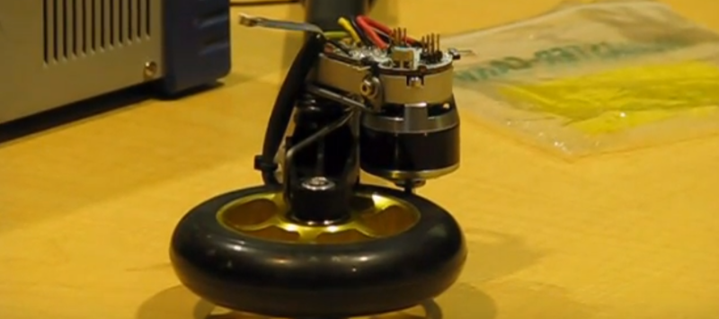
If you’re an active shopper on RC websites, you’ll find tiny motors spec’ed at hundreds of watts while weighing just a few grams, like this one. Sadly, their complementary motor controllers are designed to drive them at a high speed, which means we can only hit that “520-watt” power spec by operating in a max-speed-minimum-torque configuration. Sure, that configuration is just fine for rc plane and multicopter enthusiasts, but for roboticists looking to drive these bldc motors in a low-speed-high-torque configuration, the searches come up blank.
The days in the dust are coming to an end though! [Cameron] has been hard at work at a low cost, closed-loop controller for the robotics community that will take a conventional BLDC airplane motor and transform it into a high end servo motor. Best of all, the entire package will only run you about $20 in parts–including the position sensor!
“Another BLDC motor controller?” you might think. “Surely, I’ve seen this before“. Fear not, faithful readers; [Cameron’s] solution will get even the grumpiest of engineers to crack a smile. For starters, he’s closing the loop with a Melexis MLX90363 hall effect sensor to locate the rotor position. Simply glue a small magnet to the shaft, calibrate the magnetic field with one revolution, and–poof–a wild 14-bit encoder has appeared! Best of all, this solution costs a mere $5 to $10 in parts.
Next off, [Cameron] uncovered a little-known secret of the ATMEGA32u4, better known as the chip inside the Arduino Leonardo. It turns out that this chip’s TIMER4 peripheral contains a feature designed exclusively for 3-phase brushless motor control. Complementary PWM outputs are built into 3 pairs of pins with configurable dead time built into the chip hardware. Finally, [Cameron] is pulsing the FETs at a clean 32-Khz — well beyond the audible range, which means we won’t hear that piercing 8-Khz whine that’s so characteristic of cheap BLDC motor controllers.
Curious? Check out [Cameron’s] firmware and driver design on the Githubs.
Of course, there are caveats. [Cameron’s] magnetic encoder solution has a few milliseconds of lag that needs to be characterized. We also need to glue a magnet to the shaft of our motor, which won’t fly in all of our projects that have major space constraints. Finally, there’s just plain old physics. In the real world, motor torque is directly proportional to current, so stalling an off-the-shelf bldc motor at max torque will burn them out since no propeller is pushing air through them to cool them off. Nevertheless, [Cameron’s] closed loop controller, at long last, can give the homebrew robotics community the chance to explore these limits.


“which means we can only hit that “520-watt” power spec by operating in a max-speed-minimum-torque configuration”
What’s the power of a motor at 0 RPM at an arbitrary amount of torque?
The article’s complaint is a bit of a “duh” moment. Of course you can’t get the full wattage out at arbitrarily low speeds because you are limited in current. The BLDC motors simply aren’t designed to run slow, and if they were designed to run slow they would have a much higher number of poles and they wouldn’t be tiny anymore.
What is actually needed is a cheap and small harmonic drive gearbox in between: https://en.wikipedia.org/wiki/Harmonic_drive
zero movement = zero (useful) work being done = zero power…
also – higher number of poles = more iron instead of copper, so you will not get the same power output
higher number of poles means normally more diameter -> more torque, often less rpm
Would love to find a “cheap” harmonic drive!
I’ve been having some success with a 3D printed cycloidal reducer with ball bearing rollers https://en.wikipedia.org/wiki/Cycloidal_drive
I’m using the plate gear design equations in here: https://www.researchgate.net/publication/245126576_On_the_lobe_profile_design_in_a_cycloid_reducer_using_instant_velocity_center
3D printed even out of PLA works okay, CNC routed out of Delrin holds up a lot longer.
At the moment I’m using a similar hall sensor and magnet and using that feedback to control the speed command to a commercial sensorless ESC. That works okay, but still won’t develop maximum rated torque at zero speed, which would be great.
Do you have pictures or a writeup of your cycloidal work? Also an interest of mine, although I haven’t 3D printed any yet.
I tried just that!
Feel free to improve on my 3d printed harmonic drive with bldc inside, all the solidworks files are here :
https://github.com/mtourne/mecha/tree/master/Harmonic%20drive
I downloaded the files and took a look — what are you doing for the wave generator? It doesn’t seem to be in the model.
I don’t think it’s present in the assembly but there should be a file for it.
It’s basically just a cup over the motor with two roller bearings that push the sine wave out.
Hit me up via PM if you have any extra questions
Hmm, power enough for an ebike?
My thoughts as well. Been trying to adapt a car alternator for this purpose without luck.
That’s like 4 or 5 times the power though isn’t it? And they’re only meant to be 60% efficient at best. Not sure if they get better as a motor.
A car alternator is in the 600 to 1200W range. Not too bad for an e-bike. But really heavy and of low efficiency – as you wrote. And it needs excitation current, which can be considered wasted.
Sorry man, but vehicle alternators are terrible for projects. Take out the rectifier and regulator circuit and scrap the rest.
I hope he gets this to work with a capacitive encoder like the CUI AMT102-V. One of the older 12-bit absolute encoders might be something to consider as well. “Milliseconds” of feedback lag is just ugly.
Honestly, the CUI ones are not much better. I have had a heck of a time tuning motors with those on them for position loop, at least. Put on a standard HEDS optical encoder and tuning was a breeze. Buried in the documentation there is a note about interpolation lag in the AMT encoders.
“Simply glue a small magnet to the shaft” – isn’t this going to unbalance the rotor and cause wobbling, or worse?
Well, yes, but if you drive it at a low enough speed it shouldn’t matter. ;)
So use the magnets already in there. No need to add a magnet.
You can buy diametrically-magnetized magnets that are perfect disks for this purpose. https://www.kjmagnetics.com/proddetail.asp?prod=D82DIA
Working on something similar. I made a small 3D printed cap that centers the magnet on the backside of the bldc.
You glue the magnet to the end of the shaft, not to the side of it.
Assuming the magnet is symmetrical, you can balance it perfectly.
It’s also possible to file the end of the (steel) shaft flat and place it between a C shaped magnetic circuit. When the shaft rotates it changes the magnetic reluctance of the gap, which can be measured with the hall sensor.
no its on the end of the shaft, so only need one – perfect balance. it does not go on outside of shaft like a magnetic encoder but on end of shaft. the sensor picks up longitudinal mag field.
been there, done that:
https://www.youtube.com/watch?v=1SH-Nsqc4YM
and sure, this is the only correct way to drive bldc motors
That looks safe. :S
I’m using an as5040 from asm. it has a lag of 48 microSeconds
http://ams.com/eng/Products/Magnetic-Position-Sensors/Angle-Position-On-Axis/AS5040
How many VA do you need to fly the chuck ? :-)
Glad I wasn’t the only one thinking this!
Look carefully, seems to be clamped to table at the back, so maybe enough to get lift off already LOL
Tried to watch the video but got too frustrated by the guy on the left constantly interrupting (and constantly being corrected by the guy on the right). Pissed me right off.
I work with electric power steering motors. They seem like they may be perfect for this application. Has anyone tried to use one? It could be a bit difficult to separate the ecu from the motor. You could try to use it. It does have the high current drivers in it but the CAN and soft limits in the software may get in the way. These motors have a disc magnet on a post driven into the end of the shaft for the speed feedback. I haven’t had time to experiment with them yet. I was wondering if anyone beat me to it.
It’s kHz not Khz…
Thanks. None of us knew what the hell [Joshua] was writing about until you cleared up the mess.
Much appreciated.
I like how there is a solution to make every engineer smile. That is what I am looking for right now. Maybe I can find this solution and try it out myself.