We have a love/hate relationship with LiIon batteries. They pack all this power in such a small and light package. But for running 3.3 V devices, they’re cumbersome. They need to be stepped down a little bit when they’re fully charged at 4.2 V, but then they need to be stepped up at the end of their charge around 3.0 V.
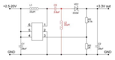
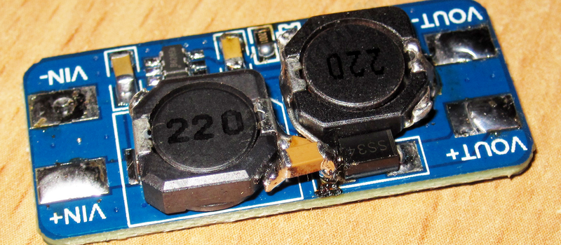
A simple boost or buck converter can’t do both jobs, although you’d be tempted because they can be purchased for peanuts online. So [Kirich] hacked cheap boost converters into the more capable SEPIC topology, which sell for nearly 10x as much. (Google translated version here.) The bottom line? With a little desoldering, a cut trace here and an extra inductor there, and [Kirich] had a very capable circuit that would maintain a constant 3.3 V output when the input swung between 1 V and 5 V.
 If SEPIC power converters are foreign to you, have a read through Maxim’s white paper on the subject. Basically, it’s a boost converter with a capacitor in the middle that lets the output voltage drop below the input voltage. An extra inductor keeps the output side of this capacitor at ground potential (on average).
If you want more detail, [Kirich] doesn’t disappoint. He tested his modifications in multiple configurations on two different models of boost converter. As you’d expect with power circuitry, layout and trace length matters, and [Kirich] took good notes. This is a great read for the frugal hacker, or anyone who’s interested in boost/buck converters.
Speaking of boost/buck circuits, we’ve got some more links for you. This video from Sparkfun’s [Pete Dokter] is worth fifteen minutes, and if you want to get your hands really dirty in the construction of such circuits, this ATtiny-based boost converter circuit is fun to play with.
Thanks [kirillre4] for the great tip!


That’s cute, but how much can be spared when a 1.25-35V/3A SEPIC is just $2 including shipping?
http://www.aliexpress.com/item/DC-DC-buck-module-4-30-rpm-1-25-35V-Adapter-Auto-Boost-Buck-solar-panels/1407047461.html
Minimum input voltage on those is 3.8V
This makes SEPIC converters look a lot simpler than I thought. I’ve become familiar with buck and boost. Now it looks like it’s time to take the next step…
They are simple up to the point you want to simulate them…
I will call this boost the bang per buck…
Might be interesting: http://schmidt-walter-schaltnetzteile.de/smps_e/smps_e.html
Also, this one: http://www.ti.com/lit/sg/sluw001e/sluw001e.pdf
The SEPIC converter has a slightly lower efficiency than a buck converter. You have to work out the efficiency to see if you ended up getting better or worst battery life just to get that last little part of the discharge curve. The Li-ion battery will get better cycles if you don’t discharge it all the way down.
A buck converter that can handle 100% duty cycle will go into drop out mode when the input is below desired load. It’ll basically connect the load directly to the battery. A lot of chips designed for battery operations these days are spec to 2.7V or lower. Unless the parts really need to have 3.3V +/- 5%, there is no reason not to go lower.
You are looking at a small percentage of the battery capacity assuming that the efficiency for a buck is the same as a SEPIC. Unless you SEPIC efficiency is within that amount than the buck converter, it really doesn’t buy you anything.
https://www.maximintegrated.com/en/app-notes/index.mvp/id/471
“Step-up Converter with LDO Beats SEPIC Efficiency”
Something to think about.
Thanks for the link!
The summary is that the SEPIC has ~85% efficiency across the voltage range 4.2-3.0 V, while a step-up converter, followed by a linear LDO regulator is around 80% worst-case, but then 90% best case at around 3.6 V (for higher loads). Since a LiIon spends a lot of its discharge around 3.6 V, it can actually make sense to step the voltage up first, and then drop it down with an efficient linear regulator.
Who knew?
“efficient linear regulator” isn’t that an oxymoron
It’s efficient when it’s operated as closely as possible to it’s dropout voltage.
In that case what’s the LDO required for? Couldn’t you just design the step-up converted for the desired output voltage?
The idea is you use the step up to say 4.5V (from 4.2-2.7ish), and use the LDO to drop from 4.5 to 3.3. If you just have the step up go to 3.3, then it won’t work from 3.3-4.2V, where the battery sits most of the time.
@simcop2387, thanks for your reply.
So that’s useful when using LiPo batteries.
What about a step-up converter operating from [0.1V to 3V] => 3.3V, that way a button battery could be used with 3.3V logic until totally depleted.
I think lots of batteries are considered empty too soon. My wireless mouse stops working when the 2 AA batteries drop below 1V (I don’t know the energy distribution so I don’t know if by that time 95% of usable energy has been used, but assuming with a linear distribution -most likely wrong-, a 1.5V battery would still have 2/3s of energy when it reaches 1V)
Wow. I incidentally ended up using this topology for a project, and I thought it was a shame I couldn’t do it “properly”. Little did I know!
“Russian hacker” in the title is bound to be an exercise in frugality.
The only fault: he isn’t _russian_.
The post was in Russian, on a .ru website. How can you tell he’s not russian?
You’ll have to forgive your (ignorant) author for making assumptions. Apologies [Kirich], if you’re out there.
From user profile on said site? It is public.
I am from Ukraine, but I write and speak Russian :)
Hey. I am the author of this improvement, I am pleased that it turned out to be useful for other readers.
If you have questions, I can answer.
I’ve no question, but I want to let you know this inspired me with my current project. Thank you for sharing your work!
Cool! I did notice that one big problem with solar panels is a 5 degree angle change can give a 60% increase in power.
I have a possible fix, let me know if you are interested.
Its actually incredibly simple and leverages existing components, can be added to existing setup and uses many recycled materials!