
Resistors are one of the fundamental components used in electronic circuits. They do one thing: resist the flow of electrical current. There is more than one way to skin a cat, and there is more than one way for a resistor to work. In previous articles I talked about fixed value resistors as well as variable resistors.
There is one other major group of variable resistors which I didn’t get into: resistors which change value without human intervention. These change by environmental means: temperature, voltage, light, magnetic fields and physical strain. They’re commonly used for automation and without them our lives would be very different.
Thermistors
They come in two types:
- NTC, or Negative Temperature Coefficient thermistors, where as the temperature increases their resistance decreases, and
- PTC, or Positive Temperature Coefficient thermistors, where as the temperature increases their resistance increases.
Many Hackaday readers might be familiar with NTC thermistors in 3D printers where they’re used to measure the temperature of the hot end of the extruder. If your printer has a heated bed it is likely also monitored by an NTC.
And there are many more applications where they’re used for measuring temperature such as in digital thermometers, toasters, coffee makers, freezers, and so on.
But in addition to measuring temperature, NTC thermistors are also used for limiting current. As inrush current limiters they limit any rush of high current when a device is first turned on. Basically when the device is turned on, the thermistor is still relatively cool and so acts as a high resistance, limiting the current. Over time, as more current flows through the thermistor, its temperature increases and so its resistance decreases. That allows more current to flow through it, which is fine since the initial rush of high current is finished by that time.
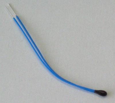
My only experience with NTC thermistors was to play around with one that was part of an automotive sensor. The sensor was to be screwed into the engine compartment possibly for measuring the coolant or oil temperature. Of course this doesn’t measure the temperature directly. Instead a voltage is applied across it. As the temperature changes, the resistance changes and so does the voltage. The vehicle’s computer then uses a table or formula to map that voltage to a temperature.


I couldn’t find the datasheet for the automotive part and didn’t know the relationship between the thermistor’s temperature and resistance so I put it in a pot of water on the stove. As I slowly brought the water to a boil I measured the water temperature and the thermistor’s resistance, obtaining the chart shown here.
Positive Temperature Coefficient (PTC) thermistors, whose resistance increases as temperature increases, also have their uses.
One example is as a replacement for a fuse. As the current in a circuit increases, the temperature of the thermistor increases due to normal resistive heating. This heat is lost to the surroundings. But if the current is higher than it should be then at some point it will heat up faster than it can lose that heat. At that point the resistance will increase, limiting the current.
With the advent of flat panel displays there are fewer and fewer CRT displays around but some readers will remember that PTC thermistors were used in the display’s degaussing coil circuits. The degaussing coil would need to be energized briefly and turned off gradually. The current through the coil would create the needed magnetic field for degaussing, and the current would also heat up the thermistor. As it did, the thermistor’s resistance would increase in the desired gradual manner, reducing the current through the coil until the circuit shut off.
Varistor
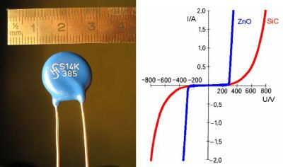
Most applications for varistors are in surge protection, protecting circuits from mains transients, inductive loads and from lightning. They’re usually placed across the circuit to be protected so that should the voltage rise high enough across it, the varistor will conduct and act as a short for the current, instead of the current going through the circuit.


My own experience with varistors comes from my time as a solar contractor. We’d attach lightning arresters to various components of the solar system: two arresters for the inverter, where one set of wires ran outdoors to a generator and another set went out to the loads in the cottage, and one arrester for the charge controller where wires ran out to the solar panels. These are all wire runs where voltage can be induced to damaging levels by nearby lightning.
Each of these lightning arresters contains a Metal Oxide Varistor (MOV). The varistor is connected between the wires and ground. As long as the voltage is low enough then current doesn’t conduct. But when lightning strikes somewhere nearby, the voltage on the wires rises and reaches a point where the varistor conducts to ground (e.g. 385 volts). This prevents the voltage from rising further. As long as the solar component is able to handle that voltage then it’s protected. With some standards, the solar component is designed to handle up to 2300 volts where these wires are connected.
Photoresistor/LDR
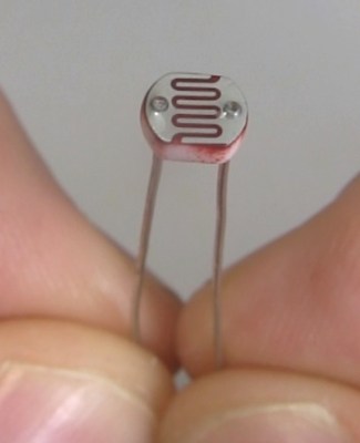
A photoresistor’s resistance decreases as light intensity increases. You may also see it referred to as an LDR (Light Dependent Resistor). Its resistance in the dark can be in the megaohms but with the correct wavelengths and sufficient intensity of light, it can be just a few ohms.
Photoresistors aren’t good for detecting rapid changes in light intensity. In going from complete darkness to light, there can be as much as a 10 millisecond delay before the resistance decreases fully. And when going from light to complete darkness the resistance can take as much as 1 second to increase to the megaohm range. However, there are applications where this delay is desireable such as with audio compression. Here an LED or electroluminescent panel is used to control the resistance of the photoresistor and affect the audio signal gain. Doing so is said to sound smoother by softening the attack and release than doing so without a photoresistor.
Another typical application is for a light sensor to detect if a night light should be turned on.
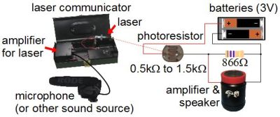
In my case I made a laser communicator that used an audio signal to modulate the output of a dollar store toy laser. I then shined that now fluctuating laser beam onto a distant photoresistor. The photoresistor was part of a circuit that fed an amplifier and the result was the audio signal transmitted by light and reproduced on the amplifier’s speaker. This violated what I mentioned above about not using them for rapid changes in light intensity, but it worked well enough as a fun experiment.
Magneto Resistive Sensor
The resistance of a magneto resistor can be used to detect the position, orientation and strength of a magnetic field. It uses the magnetoresistance effect. The anisotropic magnetoresistance (AMR) effect, discovered in the 1800s is sensitive to the magnetic field strength and the angle between an electric current and the magnetic field. There are other, more recently discovered effects but most conventional resistors use the AMR effect. Magneto resistive sensors that are built around these resistors are available from Digikey and Mouser among others.
I haven’t used magneto resistive sensors myself but one common application is as wheel speed sensors in automobiles. Others are magnetometry, various sensors for angle, rotation and linear positions, and for detecting vehicles on the road.
There is a lot of interesting potential applications for these sensors. At the 2013 Open Hardware Summit a 1-DOF haptick feedback kit called Hapkit was demonstrated by a group from Stanford. They used a magneto resistive sensor to detect a pendulum’s position. That position is then used by a microcontroller to power a motor to make moving the pendulum by hand feel like you’re moving a spring or click wheel.
Strain Gauges
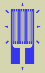
The change in resistance is very small and so to aid measurement the strain gauge is incorporated in a Wheatstone bridge. A full article could be written about strain gauges and their use in Wheatstone bridges so here’s just a brief overview.
The Wheatstone bridge consists of two voltage dividers, R1 and R2 being one of them, and R3 and R4 being the other one. The input voltage, called the excitation voltage (VEx), is across the outside of the bridge, and the resulting output voltage (Vo) is taken from the centers of the two voltage dividers.
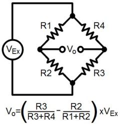
The voltage output, Vo, can be calculated using the formula shown. If the ratio R1/R2 is equal to the ratio R4/R3 then calculating Vo you’ll find you get 0 volts. But if one of the resistors is replaced with a strain gauge then when it’s strained, Vo will become non-zero. Further formulas can be used to convert this to a value in a unit actually called ‘strain’.
Multiple strain gauges can also be used to further amplify the values and to compensate for temperature.
Strain gauges are found in load cells and pressure sensors, both often incorporated in Wheatstone bridges. The ones in pressure sensors are usually made with silicon, polysilicon, metal film, thick film or bonded foil.
Conclusion
And that concludes this series on resistors. The other two articles are on fixed value resistors and on variable resistors that are manipulated by human intervention. Check them out if you missed them. And let us know in the comments of any resistors that we missed along the way or of anything you’d like to add.


“There is more than one way to skin a cat”… I HATE that stupid expression. How would you feel if you read “There is more than one way to skin a dog” or “There is more than one way to skin a baby”?
I wouldn’t care in both cases tbh.
Except for the fact that I never heard the expression and would probably think the author meant:
“There is more than one way to skin a cat”.
Steve takes this personally . . . because he’s a pussy.
https://c2.staticflickr.com/6/5108/5611007702_c1e0f31e2f.jpg
Nope.
Everybody knows you are a dog.
I would feel confused, because those aren’t the phrases that everyone uses.
Ironically, there are multiple meaning to the phrase “There is more than one way to skin a cat.” You can find a few here: http://www.phrases.org.uk/meanings/there-is-more-than-one-way-to-skin-a-cat.html
I throw variations of that all the time, after all there is more than one way to melt steel beams.
Not jet fuel.
They just didn’t melt. It was enough for the building to crash, that the steel softened. And that needs only half of the temperature than to melt it. You can ask any blacksmith about this properties of steel.
LOL, next you will be complaining that the expression “fat cat” is a form of fat-shaming.
It’s a form of cat shaming.
I’m guessing the term “cat skinner” get you going as well. ;) Ah life’s small stuff not to sweat, but it’s no surprise someone sweats it. Hop your day gets better as it goes along.
HMMMMMMM! Baby Skin, Tasty!
http://art-bin.com/art/omodest.html
Don’t be such a Karen.
“In a varistor the higher the voltage, the higher the resistance,”
Doesn’t resistance drop as the voltage increases? Otherwise it would short circuit your supply with low voltages, and voltage spikes would go marrily on to your circuit…
Thanks. Fixed. Too many if this goes this way then that goes that way in this series. Makes it harder to proof. :)
A quick comment on photo resistors. Most of them use cadmium, which is considered toxic, and may make them hard to find in some countries. From the Wikipedia article:
“The use of CdS and CdSe photoresistors is severely restricted in Europe due to the RoHS ban on cadmium.”
https://en.wikipedia.org/wiki/Photoresistor
Sweet, I’m building everything with ORP-12s to make half the world jealous then. ;-)
Do you know if there’s a drop in solution? I’m having trouble accurately measuring ambient light cheaply without using a LDR. Photo-diodes seem much more expensive and rarely ambient sensitive?
It’s not nearly as simple (the output is frequency), but a TSL235R is cheap and gives accurate, repeatable and linear light-level measurements of the visible spectrum.
I guess if you wanted to stay all-analogue and avoid a microcontroller performing a period/frequency measurement, you could trigger a fast monostable from the TSL235 and then low-pass filter the resulting PWM signal :) Yuck.
Try a cheap (small) solar cell and put a resistor in parallel with it, then sense the voltage drop across the resistor. Or take a look at the OPT101 from T.I. (may be too expensive).
A cheep LED will do it.
http://laser.physics.sunysb.edu/~tanya/report2/
Hello. Do you know of a drop in replacement? I’m finding it hard to find a cheap light sensor that’s legal at the moment. Photo-diodes seem to be expensive and rarely ambient light sensitive?
I don’t think so. A friend working for a major consumer electronics company mentioned that their EU version of the product had to use photodiodes instead of photoresistors.
Photodiodes aren’t expensive. You can get 20 pcs for $1 in 3mm package (similar to a LED) with free shipping. Not a drop in replacement, but there are ways of getting it to work with minimum components.
In fact, a standard led can be used as a weak photodiode.
“But if the current is higher than it should be then at some point it will heat up faster than it can lose that heat”
………….. heat up faster than it can’t lose that heat ”
Right?
“than” is used for comparisons. In this case comparing how much heat it produces to how much it can lose. You’re statement would be correct if you used “then” which implies a sequence or cause and effect.
No. “…can lose heat…” is correct. Think of the ability to lose heat as the same as the ability to cool off.
So, if it heats up faster than it can cool off, the current is too high.
Beefy PTC resistors are also well suited for use as heating elements, given they’re voltage or current limited
Aren’t all heating elements PTC resistors to at least some degree? Even in normal heating elements the effect is pretty substantial (Look at loads in series with heating elements, and the huge power surges through them as the heater warms)
*Most* heating elements are PTC but not necessarily resistors. Incandescent light bulbs generate heat but are NTC.
No, they have a very strong PTC effect. The resistance of the Tungsten increases about 10 fold when they light up/heat up. An exception were the ancient carbon filament bulbs, carbon has a negative TC.
I used a Goot temperature controlled soldering iron back in the 80’s that uses PTC heating element. The PTC regulates it own temperature and it was decent and cheap.
A lens and a grid of nickle chromium wires can be used as sun position detector with no moving parts.
But that seems to need a complicated multichannel sense amplifier solution. These days I would use a cheap camera chip and a small lens or even just a pinhole.
“Aren’t all heating elements PTC resistors to at least some degree? ”
There are some puns buried in there. Nice work.
A wire coil in your hair dryer is not a PTC resistor. Put enough power through it and it will melt and open circuit (behaves like a fuse.)
The PTC part means that the resistance actually rises as the power dissipated by the resistor increases. This is a self-limiting characteristic. PTC effects for the rdson of silicon MOSFETs is the reason you can parallel them.
For a fixed voltage power supply, or constant current power source a PTC resistor would serve to self-regulate. As the power dissipation increases, the PTC resistance would increase, there by limiting its power dissipation. This could also be due to an elevated ambient temperature for example.
A regular carbon resistor doesn’t have this PTC property.
PTC stands for positive temperature coefficient. All metals and some non-metals (including carbon) have a positive temperature coefficient. In this case PTC specifically refers to semi-conductor devices designed to limit current by increasing their resistance.
Not all resistors make self-limiting heating elements, as you pointed out. Some do – some quick wikipedia action on “heating element” suggests that the rear window defroster elements on cars work this way – positive temperature coefficient and a fairly non-linear response to boot.
” or constant current power source”
That part is wrong.
Constant current sources have limited compliance voltage.
PTCs only self regulate with a constant voltage source. With a constant current source self regulation is only possible with an NTC. Higher temp -> Less resistance -> less voltage drop -> less power
I don’t think you could describe a PTC as a fuse. The resistance ratio of a PTC is too low for it to act like a fuse. A poly switch has a much higher resistance ratio and is more “fuse like” but neither of these things can be called a “fuse” because they don’t isolate.
Also – the most inventive place I have seen a LDR was in an old computer monitor. The designer must have had a dislike for potentiometers. The brightness and contrast controls consisted of a LED and LDR with a strip of movable plastic between them. The plastic was graduated from transparent at one end to opaque at the other. Sliding a control moved the plastic. Very Rube Goldberg like but had far less sensitivity to dust.
Can’t think why anyone would do that. Unless the would-be potentiometer had to be very, very reliable. But even an ordinary one should outlast the CRT.
Only thing I can think of, is tiny tiny sparks if the wiper lost contact with the carbon trace. For use in ludicrously explosive environments. But then, CRTs are high voltage, which you also don’t want around explosives.
Real puzzle, that.
Pots don’t do well with dust. Have you ever heard a “scratchy” volume control on old equipment.
The wiper of a pot provides a wedge shaped part for a simple speck of dust to isolate the wiper from the curved resistor. For this reason pots often had 2 or 3 wipers but even those needed a bit of a clean out and re-lubrication from time to time.
The optic setup mentioned is impervious to the effects of dust. I have seen PC boxes with an inch of dust at the bottom and still working so that gives some idea of just how much dust is on some industrial sites.
And … believe it or not a CRT can last a very long time. They can re-rejuvenated when they get dull and you can do that several times.
Nice article. Hackaday does produce some rather good content from time to time.
What I like about it: Concise explanation, gives a good overview of the topic. Could it be written better? Of course, but most writing can be improved. However, I like it as it is.
Some of the stranger variable resistors I’ve encountered are humidity-sensitive resistors. They are used for measuring the humidity of ambient air, and are usually made from some special polymer. Manufacturers recommend measuring their AC resistance at a certain frequency (10 kHz or so) to get the humidity. The venerable DHT11, pretty much the go-to cheap-as-dirt humidity measurement solution for tinkerers, has such a resistor. You can see it quite clearly on a picture of it (e.g. http://store.iteadstudio.com/images/icon/Humidity%20temperature%20sensor.JPG)
And then, there are resistors sensitive to some chemicals. Their resistance changes as certain chemicals attach to their surface, so they are used as inexpensive gas detectors. They usually need to be heated, however.
I read a long time ago in an electronics magazine, how to make your own humidity sensor. Because they weren’t easy to get hold of at the time I suppose (late 1980s).
It used a strip of paper soaked in some ionic solution, some salt, then left to dry. It had to be driven with AC, because DC current would cause electrolysis. Over time, that would separate the chemicals and ruin the sensor. With AC, any ions ripped free on one half-cycle were put back again on the next. That’s probably how the one you mention works, some type of salt ions dissolved in a base substance.
There used to be a guy who ran around campus in a pink tutu, ballet slippers and a turban. Turns out he invented the strain gauge, there was a dispute over the patent, and I was told that the attire was his way of protesting (ultimately somewhat self-destructive).
https://en.wikipedia.org/wiki/Edward_E._Simmons
Apparently, the story of the strain gauge is a bit more convoluted than even that, though:
https://en.wikipedia.org/wiki/Arthur_Claude_Ruge
Apparently the invention caused more strain than it measured. (Sorry, couldn’t resist.)
Couldn’t take the strain. The strain was too much for him. And I’m done.
Actually Simmons lived to 92 or 93 (it says on Wikipedia) and Ruge to 95. And Simmons won his patent case in 1949, against Caltech who tried to claim ownership. So whatever the ballet gear was about, it wasn’t a protest. Unless he was still really really pissed off 50 years later about a case he’d won. Just to teach them a lesson.
Ruge invented his strain gauge to measure simulated earthquakes. But he didn’t crack up under pressure (tip your waitress!)
You might want to add a quick blurb about thermocouplers even though they voltage instead of resistor components. Thermocouples are more often used for temperature measurements.A thermistor is a temperature-sensitive resistor, while a thermocouple generates a voltage proportional to the temperature. Also, thermocouples can work at much higher temperatures than thermistors.
There are two common families of thermocouplers; J or K.
https://en.wikipedia.org/wiki/Thermocouple
A nice temperature graph is…
https://en.wikipedia.org/wiki/Thermocouple#/media/File:Intermediate_temperature_thermocouples_reference_functions.svg
I’m making a colloidal silver generator so is there an automatic variable resistor that automatically adjusts to maintain a constant 1mA of current as the resistance of the water the electrodes are immersed in lowers with increasing silver content?