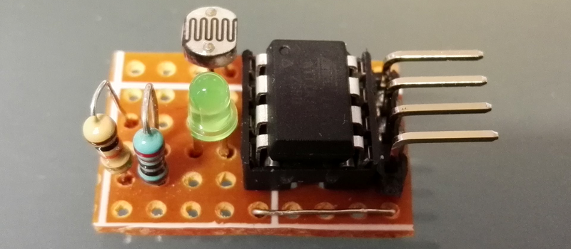
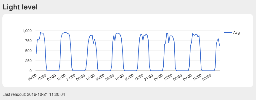
[Pawel] has a weather station, and its nerve-center is a Raspberry Pi. He wanted to include a light sensor but the problem is, the Pi doesn’t have a built-in ADC to read the voltage off the light-dependent resistor that he (presumably) had in his junk box. You can, of course, buy I2C ADC chips and modules, but when you’ve already got a microcontroller that has ADC peripherals on board, why bother?
[Pawel] wired up a tremendously simple circuit, downloaded some I2C slave-mode code, and added an LED for good measure. It’s all up on GitHub if you’re interested.
We’re covering this because we rarely see people coding for I2C slave devices. Everyone and their mom uses I2C to connect to sensors, for which the Arduino “Wire” library or “i2c-tools” on the Pi do just fine. But what do you do when you want to make the I2C device? [Pawel]’s project makes use of TinyWireS, a slave-mode SPI and I2C library for AVR ATtiny Arduino projects.
Here, [Pawel] just wanted a light sensor. But if you’re building your own devices, the sky is the limit. What’s the most esoteric I2C sensor that you can imagine? (And is it really the case that we haven’t seen an I2C slave device hack since 2010?)


I did big, multiplexed 8×8 touch keyboard with RGB LEDs. It was supposed to work as I2C slave, but I had big problems with the code for it. Example I2C slave code for PIC micro didn’t really work, and not only for me. I abandoned it for few months, but I might try to make it work…
Hmm, attiny85 as a slave and a raspberry pi as a master is trouble — rpi has bug in its clock-stretching hardware, and with the attiny not being a daemon of speed, you are going to hit that sooner or later.
Actually, as the ATTiny is pretty much being dedicated to one function, the chance of hitting this bug is zero. The ATTiny shouldn’t have any problem in responding in time and never stretch the clock.
You can also lower the I2C clock speed on the Pi to give you even more time.
i never had any problems. of course i just used it as a 2 axis 1 button joystick, its driver scanned it at roughly 60 times a second, scanning out 3 bytes. the device spent most of its time in an eternal loop waiting for a command. it would only ever do actual work when it was given the update command, and then the output would be stuffed into its registers and could be retrieved with the read command. im sure if you were moving more data or doing more frequent update you would have issues, but i never encountered any.
That’s pretty much exactly what i was planning on doing. I wanted to build a camera rig controller with four (yes, four as in 4) 2axis1button sticks giving me 8 axis control. I’ve already made the two “wings” each of which incorporates two of those sticks connected to one Attiny. Those were supposed to be connected to a “mainboard” of sorts in the middle which in turn was supposed to pack an atmega32u4 (AFAIR), a display and a radio module. Then i started reading up on I2C slave mode and then procrastination hit me like a freight train.
May end up picking this one up again after reading this article and your comment.
Even better,
The RPI3’s I2C clockspeed lowers itself. Have fun with that.
You’re better off taking a microcontroller and talking to it through the REAL UART on the pi.
I’ve never got TinyWireS to work, maybe its the core I use, i prefer arduino-tiny to attiny, unless its the rpi bug dassheep mentions as that would be my master
the first time i gave it a go, and i also couldn’t get it to work and gave up. then, some years later, i used the callbacks and now it works like a charm. just register them right after TinyWireS.begin() using TinyWireS.onReceive() and TinyWireS.onRequest(), both take a function for their respective events.
you need a request event, and all that does is send the data in the current register (just an array and an index variable), and increments its index (thus subsequent events can read out the entire array, in typical i2c fashion). it only cares about the one byte at a time and will be called multiple times to get more data.
the receive event is more complicated. it has to be able to handle multiple bytes. it has a count argument to tell you how many. the first is always the index into the register and subsequent bytes are things being written into registers starting at that index, like config data. mine is dumb and it just writes the data, but you can throw in some logic to check to make sure a register is writable or if the data needs to be qualified before being written.
the loop pretty much updates the registers, mine just reads the adcs, packs it into 3 bytes (2 lsbs in the first 2 bytes, the top 2 bits for each axis and the button state and 3 bits of padding go into the third). the catch is you cant write directly to the registers without disabling interrupts and you cant disable them for long either. so write your data to a temp register and copy it over between cli() and sei(). since i2c is interrupt driven, you really dont have to worry about hogging all the cpu time. the callbacks handle everything that needs handling.
All good as long you’re not using clockstretching on the AVR ! The I2C Interface of the Raspberry Pi is useless in this case !
http://www.advamation.com/knowhow/raspberrypi/rpi-i2c-bug.html
If the CPU load on the Pi is not that critical you can use the i2c-gpio module. This bitbangs the protocol and of course is fully standard compliant, inducing clock stretching: http://lxr.free-electrons.com/source/drivers/i2c/busses/i2c-gpio.c
“The I2C Interface of the Raspberry Pi is useless in this case ”
Well better throw that 10 million pi’s in the bin…Rather a hyperbolic statement don’t you think? There are many workarounds. Just needs some imagination……..
You can use two avr’s (or any other small uC) for i2c-to-i2c communication, the second one will then output serial data to rpi or any other device like pc. if it’s too much, there’s $5 i2c sensors on ebay to connect directly to rpi.
Where is the decoupling cap? Really guys, it’s not worth leaving out, intermittent failures are not fun.
A project I did a long time ago is/was my “frontpanel”.
It is a combination of HD44780, (upto) 8×8 buttons, (7-segment) LED’s, a few encoders & potmeters all connected to an atmega.
It basically has almost everything you’d want for a frontpanel of a (benchtop) measurement device.
The main reason for starting the project was that the keypad scanning caused too much noise in the analog circuitry.
A very big advantage over I2C over SPI is the built-in limited slew-rate.
This also results in a clean wiring solution to the front panel and freed up a lot of pins on the main project.
Later I discovered an extra advantage. This frontpanel project could easily be added to a breadboard to provide a ui to any circuit you’re working on.
On one of my robot projects, the whole motor controller is an I2C slave device. I’m working on building sensor clusters for it using ATTINY85’s which also will be I2C slave devices. On another project that I built, a frequency generator, the front panel was built as an I2C slave sub-assembly using an ATMega328p (essentially an Arduino).
On another robot some years ago, I made “custom chips” using the capabilities in PIC controllers, such as a “turret controller” assembly, and interfaced to it using SPI– yeah, I know, technically not I2C, but more or less the same idea (the 68HC11 did not have I2C built-in).
I made I2C slave Arduinos with RFID readers so that I could have a network of RFID readers in a small room (quest room wonders…). It worked, and better than expected.
Why is not possible to do that with the “official” Arduino Wire library?
Your question is a bit ambiguous: do you mean “do that” as in making an I2C-slave with the official Arduino Wire-library, or do you mean using the official Wire-library with Attiny85?
For the first question: you can. The official Wire-library does allow you to make I2C-slaves and masters.
For the other question: because none of the Attiny-series chips are official supported. Also, the serial-peripheral the Attiny-series chips have is a more generic kind of a thing that can act as UART, or I2C, or SPI etc., and as such you can’t just grab the Atmega I2C-code and use it with the Attiny. That is to say, you need an Attiny-specific Wire-library.
The “official” Arduino Wire library is not compatible with the ATTinys
Small, cheap, easy to start, enough powerful for many tasks, even for implement simple USB devices like HID or mass storage devices. I use Attiny in my cheap RC lap counter project – sadly not done yet
I once wrote the code for an I2C 8×8 keypad peripheral that produce XT keycodes for press and release. It was meant for use with an SBC that used a NEC V51 “XT-on-a-chip.” I also did an I2C LCD peripheral for the same SBC.
FYI I recently modified a library for ON Semiconductor I2C EEPROMs (ie CAT24M01 256kbyte: http://www.onsemi.com/pub_link/Collateral/CAT24M01-D.PDF) that works with TinyWireM for I2C and the ATTiny85. There is a new function that allows you to use a ‘read next byte’ method to get data quickly over TinyWireM. I haven’t published it but let me know if you’re interested it works well with sound clips for PWM audio applications.
This is very nice. :)
I built a low power BLE wireless accelerometer with the attiny85 + TinyWireM + SoftwareSerial. Works perfectly.
I also built a small communicatuon stack on top of the SoftwareSerial.
The I2C was connected to an MPU6050 six-xis gyroscope and accelerometer.
I did have fun!
For extra hack value, should have used the LED as the light sensor.
I made some I2C light switches with an ATtiny45. They consist of a status LED and SSR to switch mains on and off.
An Arduino is used as master device.
In a web frontend you can select which light to turn on/off. The backend sends commands over USB to the master Arduino which in turn forwards them to the I2C slave devices.
I think the idea can be used to implement a “Multiplexor Server” for a cluster of simple sensors. Say, I want to have 8 analogRead() type of sensors on an Arduino Nano where I do not have enough analog pins. This way I can serve them all on two pins.
Here is a fairly well written example for the Attiny85, using it as an I2C slave device that turns it into a 2-channel analog + one pwm output device. It has an example code that could be used on the master as well in the comment section.
https://gist.github.com/Rawze/61df2bd9e86b131faeb5140005507520
Excellent job for a cheap Digispark board ( http://s.click.aliexpress.com/e/ZJyn2je ). Came with USB bootloader, so no hardware programmer needed. A low cost and very compact slave for the I/O tasks thath te RPi arn’t good.
In itself a good idea, but for ADC not an economical decision: a 12 bit i2c ADC costs maybe half of what an 85 costs. 85’s are seriously overpriced. If you get a DIL might as well get an entire pro mini to do the work