DIY I2C Devices With ATtiny85

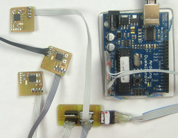
[Pawel] has a weather station, and its nerve-center is a Raspberry Pi. He wanted to include a light sensor but the problem is, the Pi doesn’t have a built-in ADC to read the voltage off the light-dependent resistor that he (presumably) had in his junk box. You can, of course, buy I2C ADC chips and modules, but when you’ve already got a microcontroller that has ADC peripherals on board, why bother?

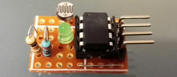
[Pawel] wired up a tremendously simple circuit, downloaded some I2C slave-mode code, and added an LED for good measure. It’s all up on GitHub if you’re interested.

cropped_shot_2016-10-21-112958
Bright by Day, Dark by Night!

We’re covering this because we rarely see people coding for I2C slave devices. Everyone and their mom uses I2C to connect to sensors, for which the Arduino “Wire” library or “i2c-tools” on the Pi do just fine. But what do you do when you want to make the I2C device? [Pawel]’s project makes use of TinyWireS, a slave-mode SPI and I2C library for AVR ATtiny Arduino projects.

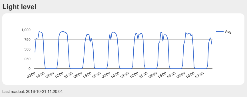
Here, [Pawel] just wanted a light sensor. But if you’re building your own devices, the sky is the limit. What’s the most esoteric I2C sensor that you can imagine? (And is it really the case that we haven’t seen an I2C slave device hack since 2010?)

Haunted Dollhouse Microcontroller Networking For World Maker Faire

master-slave-networks

It’s pretty awesome to get see the number of projects presented at World Maker Faire. But we still love digging into the gritty details that only an in-depth build post can deliver. Here we get both. You can see the circuits pictured above in the Circuit Castle exhibit at WMF this weekend, and you can read about how the microcontroller network was built in [Jim’s] article.

As the title states, this is a network built for a dollhouse. Each slave device performs a different task; adding color, sound, motion, and interactivity using some sensors.  The post discusses the i2c (or TWI to get around licensing issues as [Jim] mentions) communications used to talk to the ATtiny85 chips on the slave boards. Because the eight-pin package leaves few I/O pins to work with an ATtiny84 was also added. It brings 14-pins to the party, including multiple ADC inputs for reading sensors.

If this ends up being too much of a read for you jog to the “Update 9/17/13” to get the general overview of progress. Like any project on a timeline, not everything works quite as well as they would have liked it to. But it’s the journey that makes something like this so fun — a fully working project would signal an end to the enjoyment, right?

[via Workshop 88]