If you’ve ever tried to tune a PID system, you have probably encountered equal parts overwhelming math and black magic folk wisdom. Or maybe you just let the autotune take over. If you really want to get some good intuition for motion control algorithms, PID included, nothing beats a little hands-on experimentation.
To get you started, [Clovis] wrote in with his budget propeller-based PID demo platform (Portuguese, translated shockingly well here).
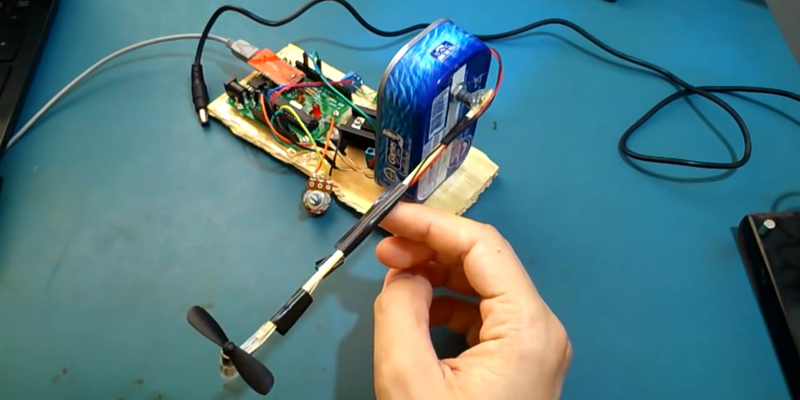
The basic setup is a potentiometer glued to a barbecue skewer with a mini-quadcopter motor and rotor on the end of it. A microcontroller reads the voltage and PWMs the propeller through a MOSFET. The goal is to have the pendulum hover stably in midair, controlled by whatever algorithms you can dream up on the controller. [Clovis]’ video demonstrates on-off and PID control of the fan. Adding a few more potentiometers (one for P, I, and D?) would make hands-on tweaking even more interactive.
In all, it’s a system that will only set you back a few bucks, but can teach you more than you’d learn in a month in college. Chances are good that you’re not going to have exactly the same brand of sardine can on hand that he did, but some improvisation is called for here.
If you don’t know why you’d like to master open-loop closed-loop control algorithms, here’s one of the best advertisements that we’ve seen in a long time. But you don’t have to start out with hand-wound hundred-dollar motors, or precisely machined bits. As [Clovis] demonstrates, you can make do with a busted quadcopter and whatever you find in your kitchen.


I am sure what this man has to tell is very interesting, but I am afraid it is wasted on most of us
Even though it’s translated shockingly well?
You may enable the captions with automatic translation to English.
I wonder why the Google page translator did such a good job on the text of the page, but the auto-translated close caption on YouTube failed so miserably. YouTube is part of Google, of course. The Translate people need to help out the YouTube people.
“The gringos are shaking.” :)
Difference is, the website was conversion from Portuguese text to English text, while the captions were Portuguese speech recognition translated to English.
Sorry, all I get from the translation is that Tony belucci and pet boy will go-go wash off on October 20 at Nile Javari and his boyfriend will control a lot of biomass int the ocean… Not very helpful and definitely not shockingly well translated unless the content creator was on acid…
haha true. I wrote that in Portuguese because I run that blog for a local public. Now that I know I have drawn attention from a broader public I may consider even re-writing it to Hackaday.io in English.
Nitpick: Since PWM is being controlled by a potentiometer attached to the output, this would be a closed-loop control algorithm. An open-loop control would be one without the potentiometer to provide feedback.
PWM is controlled by the PID algorithm. The potentiometer is used to establish the PID’s set-point.
Actually there are two potentiometers — one for measuring angle (its output goes into the PID controller which forms the closed-loop) and second to set the set-point.
Yes, I think you’re right. The pivot point for the arm is a potentiometer so the feedback from the resistance value of that pot makes this closed-loop. I’ve updated the post to correct that mistake. Thanks!
No nitpick! I must have been writing too fast. Thanks for catching it.
That is the setup designed for the 4 Weeks MIT MOOC 6.302.0x Introduction to Feedback Control Theory. Was live January this year, now renamed to “6.302.0x Introduction to Control System Design – A First Look” as an archived course.
It’s an very basic introductory level course. There they teach you step-by-step how to build all this and to program the controller. Anyone interested should take a look at the archived course and don’t be scared by the math since only the most basic you already know from HS is all what is needed.
I have seen that very briefly in the “introduction to aerospace engineering ” a month ago (and yes, That’s where the idea came from), and didn’t know it was fully featured in another course. Anyway, the way I do my stuff is “look at the end result and try to do it myself from the scratch “, so it May have elements from that course but Just look at my original Arduino code and you Will notice what I Just said
Didn’t try to imply anything negative, just liked the course and found very easy to follow so wanted to recommend it to anyone interested to learn building a PID the same as you did. :)
Kd++;
It would be cool to see this switch between PID and bang-bang control and add data out to a plot of angle versus time. One could do a really nice demo. It is nice as it is, but what are we comparing it to?
Always cool seeing closed-loop control systems in action!
It looks to me like the pot that the pendulum is connected to has a lot of friction, which may be contributing to the rather large overshoot in both directions. That, or the PID settings could be a lot better. It’s hard to tell because he didn’t demonstrate the response to disturbances in the on-off mode.
You are right Sir. The axis of the potentiometer I used has indeed a lot of friction!. I just didn’t bother to state it in the article, my bad
So I haven’t read the code Clovis uses, but this is not the best teaching or learning setup for a PID. Why? If you’ve programmed robots, especially flying robot, you’ll know that controlling the *position* in this setup needs 2 PIDs or one and a half at least. In practice you can fully control the velocity (angular rate) of the arm with a single PID. You’ll need another closed loop controller on top of the velocity controller for smooth position control, to get a behavior that doesn’t overshoot in either direction. I said one and a half because some of the P, I and D values may be 0 in the second controller.
By the way I don’t know if there’s a scientific name for such stacked PID controller, I call them PIDD (with further Ds if necessary). The velocity is the derivative of position and the derivate of the velocity is the second derivative of position, so basically this ends up being a single Proportional, Integral, Derivative, Second Derivative-and-so-on controller.
That’s ‘cascaded PID’
I’ve lifted the pid control from the Marlin 3D printer firmware a year ago, used it to create a precisely controlled heated surface using a pic mcu and converted it to use integer calculations. I’ve learned a lot tuning the pid values by hand. The animated gif on wikipedia gives a good general visualization what each variable does to the system.
The thing that I didn’t expect was that the sampljng and control frequency plays a large part in finding the pid values. Outputting the resulting data as csv through the serial port helped a great deal to graph the temperature and see what’s going on.