When looking across the discrete components in your electronic armory, it is easy to overlook the humble diode. After all, one can be forgiven for the conclusion that the everyday version of this component doesn’t do much. They have none of the special skills you’d find in tunnel, Gunn, varicap, Zener, and avalanche diodes, or even LEDs, instead they are simply a one-way valve for electrical current. Connect them one way round and current flows, the other and it doesn’t. They rectify AC to DC, power supplies are full of them. Perhaps you’ve also used them to generate a stable voltage drop because they have a pretty constant voltage across them when current is flowing, but that’s it. Diodes: the shortest Hackaday article ever.
Not so fast with dismissing the diode though. There is another trick they have hiding up their sleeves, they can also act as a switch. It shouldn’t come as too much of a shock, after all a quick look at many datasheets for general purpose diodes should reveal their description as switching diodes.
So how does a diode switch work? The key lies in that one-way valve we mentioned earlier. When the diode is forward biased and conducting electricity it will pass through any variations in the voltage being put into them, but when it is reverse biased and not conducting any electricity it will not. Thus a signal can be switched on by passing it through a diode in forward bias, and then turned off by putting the diode into reverse bias.
Diode Switch Basics
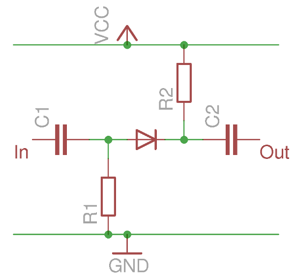
To illustrate a basic diode switch, we’ve prepared a couple of simplified circuit diagrams. The first shows the anode tied to ground through R1 and the cathode tied to the Vcc power rail. The diode is in reverse bias, and no current is flowing through it. An AC voltage applied to C1 will appear at the anode, but will not appear at the cathode and the output via C2. The switch, in this case, is off.
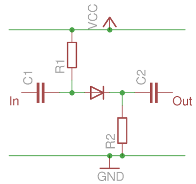
The second diagram shows a very similar circuit but with the resistors connected to the opposite supply lines. The anode is now tied to the Vcc rail and the cathode to ground. A current is flowing through the diode, and it is forward-biased. Thus an AC voltage applied to C1 will appear at both the anode and cathode of the diode, and will make it through C2 to the output. The switch has been turned ON.
This is a simplified circuit, but not by much. A practical diode switch usually works by maintain one side of the diode at a bias point so that when a logic level is applied to the other point it will switch the diode from forward to reverse bias to allow the switch to be electronically controlled. In other words, hold one end of the diode in the middle, waggle the other end high or low.
Particularly for RF circuits you will also find RF chokes in the bias lines to stop RF finding its way into the power and logic circuits. But the essence is there in the diagrams, diode switches really are that simple.
So now you know how diodes can be used as simple on-off switches. You can even make multi-way switches by connecting single diode switches in parallel to a single bias point. But that’s not the limit of the capabilities of the humble diode when it comes to switching, so we’ll now consider a couple more applications.
Diodes: They’re Only Logical
The first electronic digital computers such as those you would have found in military installations or universities in the 1940s used vacuum tubes, sometimes in conjunction with relays or other electromechanical components. As computers evolved through the early 1950s and found their way into civilian applications they started to be produced using the much smaller and less power-hungry semiconductors which were then the new kid on the block. The trouble with transistors of the 1950s though was that they were both expensive and unreliable, instead of the super-reliable planar silicon transistors we are used to today. The early 1950s designer had to work with germanium point-contact transistors. These devices, aside from their fragility, had the unfortunate characteristic of latching in the logic high state and requiring a power supply refresh after a state change. Clearly any circuitry that could reduce reliance on them was of great interest.
![The diode OR gate. Thingmaker [CC BY-SA 4.0], via Wikimedia Commons.](https://hackaday.com/wp-content/uploads/2016/11/640px-diode_or_ideal_diode.jpg)
Both diode gates use the diodes on their input lines, bringing the other ends of the diodes together at an output point with a pull-up or pull-down resistor.
The diode OR gate has the anodes facing the inputs and a pull-down resistor on the output, while the AND gate has the cathodes facing the inputs and a pull-up resistor on the output.
![The diode AND gate. Thingmaker [CC BY-SA 4.0], via Wikimedia Commons.](https://hackaday.com/wp-content/uploads/2016/11/diode_and2_ideal_diode.jpg)
It is however still worth having diode logic in your stock of available circuits, for sometimes you may have a requirement for a single AND or OR in a project and it may make sense to quickly put one together using a few diodes rather than another 74 series chip.
Mixing it up with diodes
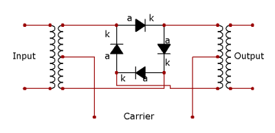
There is a further place that you will encounter a diode switch, especially if you are interested in radio or electronic music. The diode bridge mixer or ring modulator is a circuit using four diodes in a superficially similar configuration to that you’d find in a bridge rectifier, and it functions as a frequency mixer in which an AC signal and the output of an oscillator are mixed to create their sum and their difference. The four diodes act as switches between the balanced signal input and the output, and have the effect of reversing the polarity of the path between them on each cycle of the local oscillator. It is used in synthesisers and guitar pedals, and in radio circuits wherever a transition between frequencies is required.
We hope you’ll now look at those diodes in your junk box with new respect now you know they can also do a good job of switching. You may never use a diode as a switch in practice, but it’s good to be familiar with the concept. And if diodes have caught your interest, why not continue with a look at our recently-published history of the diode?


I’m a bit confuzzled about that ring modulator picture… must be the weather… ;-)
Something doesn’t look right there. Looks like it was drawn using a rectifying bridge configuration rather than a ring…
;-)
Yes, it is actually a rectifier, and in the end it would not really do it’s job.
Don’t be a ring Nazi!
That ring modulator is incorrect. It should look like this, when drawn this way:
http://webaudio.prototyping.bbc.co.uk/img/circuit_diagram_parker.png
I prefer to draw it this way, it is more obvious what is going on:
http://electronicspost.com/wp-content/uploads/2015/12/ring-modulator.png
Oops, you’re not wrong. Well spotted.
Yep, The title is “Mixing it up with diodes” and below the picture is “A diode mixer or ring modulator”.
A diode mixer is a category and and a ring modulator is a item within that category so a ring modulator is a diode mixer but a diode mixer is not necessarily a ring modulator.
The schematic shown is a diode mixer but it is not a ring modulator, it’s a different type of diode mixer as it relies on transformer core saturation and that is not the case with a ring modulator.
In a ring modulator the diodes are arranged differently so that the carrier from the local oscillator cancels itself out so the output is (F_osc + F_sig) + (F_osc – F_sig) so that the carrier frequency itself is not present in the output. This method was used to create side bands in AM transmitters. The output of a ring modulator is double side band but was hi/lo pass filtered to create single side bands like in old SSB CB transceivers.
The picture shown has the labels Signal, Local Oscillator (Carrier) and IF (Intermediate Frequency) and these labels suggest that it’s a RF modulator. I have never seen such a configuration used in RF so it seems that the picture is incorrect but it would be correct if the diodes were all cathode to anode.
I may be wrong about the above and if that is the case, this being HaD, I am sure someone will correct me.
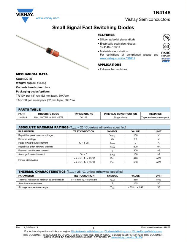
Also, in the circuit shown, the core saturation means that crossover distortion from the 0.6 volt drop across your garden variety 1N4148 1N914 is not an issue. However it’s a big issue in a ring modulator so germanium diodes were often used.
Do you have a citation for a mixer that relies on core saturation?
A ring modulator is just another name for a double balanced mixer. Diode forward voltage is NOT an issue. The Local Oscillator (often labeled simply LO) signal must be strong enough to fully forward bias the diodes with the strongest input signal expected.
In the schematic given in the article, it appears that the LO signal will NOT cancel out at the IF output, and will instead be very strong. But the Signal Input will not appear properly on the output.
No, I don’t have a citation for the core saturation but I have seen it in audio effects and music foot pedals.
How much the diode voltage drop is an issue is more about frequency than simply voltages.
Having a 12 volt peak to peak swing is not a problem at audio frequencies but try and do that 500MHz. The smaller the ratio of RF voltage to the diode voltage the more it will distort the output as this is a sine wave and not a square wave.
By sending the output of this double balanced mixer through a bandpass filter you get a DSB-SC (Double Sideband Supressed Carrier) signal which is a form of amplitude modulation. This creates the AM sidebands, as you were saying about a ring modulator. Furthermore, I am sitting with a textbook in front of me, called Modern Digital and Analog Communication Systems (B. P. Lathi; Zhi Ding), and in it it shows that same picture and calls it a ring modulator (pg. 149 in International Fourth Edition). I trust that these authors know what they are talking about and thus believe that this circuit is in fact a ring modulator. I will, however, do some more research on other diode mixers to see what else there is, so thanks for that.
The way the diode OR gate worked was obvious, but I was stumped by the diode AND gate until I reversed my normal way of thinking and thought of it as an OR gate for ground. If any A, B, OR C input is grounded, then the output is pulled down to ground (actually just above ground due to the drop across the diode) and that corresponds to a LOW or 0 on the output. Only when A, B, AND C are ALL connected to a positive voltage can the output rise to a positive voltage for a HIGH or 1.
Step 1: Build ring modulator.
Step 2: EXTERMINATE.
Came here to bring this up.
The original Dalek voice effect was created using a ring modulator and a tape recording of a 60Hz sine wave as the carrier. Lower frequencies can give you a Cyberman, and higher frequencies can give you the newer Daleks.
I built a Dalek voice box for a class project in college. Still have it.
I had no idea! Really glad I saw this.
Do you have a youtube channel? would love to see this.
I’m surprised they didn’t use 50Hz.
They probably chose 60Hz so that it couldn’t interfere with the frame sync. Or perhaps they wanted to EXTERMINATE the vertical hold in the US! :)
it looks pretty basic, i can probibly build it out of junk if i can find the right transformers. not sure what to use as the rf source, probibly stick a resistor dac on some arduino pins and have it spew out a crude waveform or something. theres probibly a dedicated variable frequency generator ic i could use instead though.
Wow, that could potentially have quite a new type of *bit crushed* sound because the analogue signal would then be a mixture of the original analog and a modified sine wave – or whatever else you choose cos you can choose anything if its coming from a micro-controller.
Would it be Digalog or Anatical?
How did i never think of using a bunch of diodes as an AND gate? Now it just seems wasteful that i used transistors or a chip whenever i needed one.
Depending upon how many gates one needs, a chip can be more space efficient, unless one wants to go “how many diodes can fit on the head of a pin” with SMD?
We need a CPLD that’s nothing but diodes.
But how would you invert a signal? And buffer a signal?
Both of those are probably possible, considering what people seam to be able to come up with…
If you also allow inductors and capacitors, it’s possible. Not sure about “nothing but diodes”
https://hackaday.io/project/11677-the-diode-clock
What logic function can’t you represent with a lookup table in a diode ROM? I think the real problem is voltage drop, you need to regularly amplify the signal somehow.
Why?
In the (19-) 70s and 80s, Harris Semiconductor made programmable diode arrays in a variety of configurations and sizes. They’re (obviously) not made any more; they never caught on because one had to be a very good design engineer in order to make use of them.
What’s different nowadays?
I wish there were a diagram that showed a circuit to hold one end of the diode in the middle, waggle the other end high or low.
https://postimg.org/image/wl79ebzdt/
It’s nice to use diodes, but I do need to ask why the diagram here uses a pull down resistor for the or gate… As technically, the pull down will be what ever one is driving with the or gate.
And using Diodes for a one of gate in a design is always nice, in worst case one needs a small inverter IC to make all types of gates. A simple NAND gate is simply two inverters connected to a diode or gate. Though, I would get a XNOR gate in an IC, rather then build it of diodes and a few inverters.
Depends on driving speed. A 1 MOhm input pin would discharge the diodes capacity maybe to slowly for your application.
Yes, in some applications it can be needed, so far I haven’t noticed any though.
I have tested running a mosfet as the device on the output of the or gate, and it worked without any pull down resistor at frequencies of around 100MHz, though, I couldn’t try it at higher speeds as I don’t have a signal generator that is fast enough. And to get rid of leakage capacitance, I floated the diodes and transistor in the air. So it should be at least a few hundred MOhms.
And it worked nicely. Though, I don’t know how it would act at a few GHz or above.
There was a time when crystal switching with diodes was common, though having separate oscillators, and switching them was also common at the time. Some argued that diodes were less than perfect, but one could get diodes better suited for that use.
Also, the ham publications showed some use of diodes to switch coils, but again with caveats. Most were using common switching diodes, while PIN diodes were a better choice.
In both cases the value was obvious. The switch could be anywhere, rather than close to the crystal or coil. And the switch became simpler, no need for multiple poles.
Michael
Organs. The Hammond and others used switch keying with it’s noisy attack. The next gen used diode keying to have a voltage keying each note at each footage for noise free AD envelope keying. Typically 61 notes, times 2 for the keyer, times 8 or 9 for footages corresponding to the drawbars on the Hammond. That’s a lot of diodes on one board with each footage a daughter board stacked side by side.
That sounds like a thing of beauty.
http://richfiles.solarbotics.net/eb/GulbransenParagonDiodes.jpg
Diodes can be used not only as switches but as current controlled resistors. Have a look at the Steiner Synthacon filter for example. The Moog transistor ladder filter is based on the same principle, the effective resistance across a silicon junction, but uses the BE junction of a transistor instead.
The pioneering HP 9100 desktop calculator used diode logic, here’s a photo: http://www.hpmuseum.org/9100/9100lg2l.jpg
Beautiful! I really was born in the wrong decade…
So much glass, and canned transistors too.
I want it.
Nice…
Silverband resistors. When “close enough” will do just fine.
Lol +1
I preface this by saying I’m an idiot. The “OR” diagram makes sense to me, but I’m confused by the “AND” diagram. It looks like current would always be flowing from +12V input to the AxBxC output, and that the diodes would do nothing at all. What am I missing?
Whenever there is any path to ground through the diodes available (all cases except 111) the input voltage will take it and you will have only the drop across the diode present at the output ~0.7 volts (logic low). When all inputs are high then the 12v input voltage appears at the output.
A must be high AND B must be high AND C must be high in order for the output to be high (and you’re correct: current flows to the output).
If any input is not high (grounded), the output is low (and current flows from the resistor to the grounded input(s)).
It may be more informative if you viewed these circuits as voltage-operated devices rather than as current-operated–even though both analyses will yield the same results.
…meant to be a reply to [chrisspurgeon]…
And [chris]–just because someone has plowed (OK; OK: ploughed) a few more rows than you doesn’t make you an idiot; only refusal to work hard and to learn can do that.
If you want to reply directly than you can click on ‘December 9, 2016 at 5:43 pm’ just under [chrisspurgeon].
(I’m not giving you a hard time, I like your input!)
I get it! My mistake was thinking that AxBxC went straight to ground when in reality of course it’s going to other downstream components not shown in the diagram.
Don’t forget about the diode as thermal sensor. Most chip sensor devices use an internal diode to measure temperature, and basically all modern CPUs and newer microcontrollers use them. The clear advantage here is that it’s very easy and cheap to integrate a diode sensor into a silicon chip design. The forward voltage of a diode is temperature dependent and that’s the effect you use in these sensors.
I was just about to add a comment about their use as thermal sensors. They make pretty good sensors actually…
I have a project in progress using a diode to sense outdoor temperature. I’m feeding a constant current through a 1n4148 and comparing the forward voltage with a reference voltage through a differential amp. Works nicely…
What are you using as your reference? Good, yet cheap temperature-stable references are worth their weight in platinum in analog design. I’ve been using TL431 / TLV431 variants as well as MCP1541’s.
A forward biased silicon junction drops by 2 to 2.2mV per degree celsius. In the past when checking heat sink efficacy, all I needed was temperature rise. So I’d use a 1N914 or a 2N2222 (collector shorted to base). I only needed the difference between ambient and the heat sink, so I was only interested in the change in temperature. When I needed a rough calibration, I’d stick it under my tongue and call that 100F or 37C. You can build a temperature sensor with nothing but a diode, resistors and a couple of 10t calibration pots and a mercury battery. Use your DMM as the display. One pot is zero set, calibrated in distilled water with crushed ice from distilled water. The other is calibrated with boiling distilled water to read 100mV at 100C. Tada! Cheap temperature probe from subzero to 100C with 0.1C granularity. Steve Greenfield AE7HD http://www.linkedin.com/in/stevenjgreenfield
I meant to say, wired up as a Wheatstone Bridge.
@AE7HD–
Outstanding and beautiful (because of its simplicity) hack! Everyone needs this in his/her archives of Really Valuable Hacks.
Well done.
Very interesting stuff for people like myself that understand the text and diagrams.well done!
You can also use the 1N4007 as a variable resistor/attenuator at RF frequencies. The turn off time is so long, an RF current “sees” it as a variable resistor, based on the DC current through it.
1N4007 tested as a PIN variable attenuation diode. Looks pretty flat from 2MHz to 100MHz, useable above and below. The 1N4007 is the only one of the 1N400x series that has a PIN structure, so the only one of them that can be used this way.
http://www.qsl.net/in3otd/electronics/PIN_diodes/1N4007.html
Wow, and a good 20dB per decade slope filter when reverse biased as well. That’s my take home from this thread.
Is there a reason that *only* to 1N4007 from the series has this attribute?
Of the 1N400X series, only the 1N4007 has the PIN structure. That means P type, Intrinsic, N type. Unlike an ordinary diode, it has a layer of intrinsic undoped silicon between the P type and N type silicon. Probably to get the 1kV PIV rating.
http://www.radio-electronics.com/info/data/semicond/pin_diode/structure.php
http://www.cliftonlaboratories.com/diode_turn-on_time.htm#1N4007
Is anyone going to correct the mixer/ring modulator schematic?
I was about to point you to a picture above and mention that the second picture is the better visualization and then I saw who posted the comment with the pics lol.
I post on different computers, and I noticed that on some I entered “Polymorph”, on some “Steven J Greenfield” and on some “Steve Greenfield”. I should stick to one.