If you’re making a circuit that is designed to plug into a breadboard, you have a problem. Those 0.1″ header pins are square, and the metal leaf contacts inside a solderless breadboard will eventually get bent out of shape. You only need to look at the breadboards in a university electronics lab for evidence of this.
The solution to this problem is to make pins that are as similar as possible to the leads on DIP chips. They should be flat, of course, and it would be nice if they didn’t have those plastic spacers and didn’t present a blob of solder on the top side of the chip.
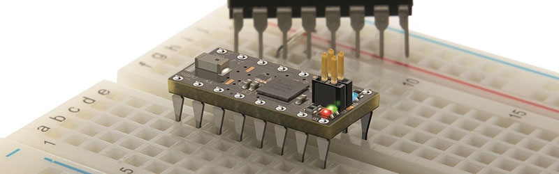
Flip-Pins are the answer. Think of them as standard pin headers, but meant for breadboard applications, and having a great aesthetic for your projects. They’re designed to look as much like standard IC pins as possible, and have the same thickness (0.020″) as standard DIP leads.
The application of Flip-Pins is a lot like soldering standard 0.1″ pin headers. The pins ship in neat little plastic retainers and can be tacked onto a PCB with just a little bit of solder. There’s a datasheet, and models for Altium, KiCad, and Eagle.
Flip-Pins grew out of another project, the OSHChip, to create an all-in-wonder chip containing an ARM microcontroller, radio, and a crossbar so any pin can be mapped to any peripheral. The OSChip itself is very cool, but one question constantly asked of the creator of this neat chip was, ‘where did you get those pins?’ From a factory. Now you can buy these pins from Evil Mad Scientist and Tindie. They’re a bit pricey, but they do look great.


When one checks the prices of breadboards, and compare to those pins, why would one want to buy those pins ?
BTW, the cheap breadboards from the world´s manufacture are totally compatible with 0.1″ headers, so this part is a useless part. Header are longer, you can run wires underneath, They are also stronger, and do their job, while DIP pins have been never been intended to be inserted, but soldered.
Those pins will likely suffer of the exact same problem than DIP pins: if their are not perfectly aligned, some pins bend under while you insert the chip.
This wonderful new part has no use, except “looking like” DIP pins, being inserted on a DIP support, or providing free advertising to your friends from OSHPark.
Much easier solution, put your DIP chips in a socket with round pins: http://toscos.com/product_images/r/838/I.C.SOCKET_ROUND_40_PINS__37285_zoom.jpg
Most likely also a lot cheaper.
I do not use header pins for use on breadboards but go for the so called “turned” header pins. If a module has the square header pins I unsolder those and fit the turned pins. I usually buy them in bulk from china, yes, no idea on the quality but same goes for header pins. I have found a fair share of square header pins that are magnetic, so probably not made of copper or bronze but steel or iron.
The only advantage I can see of these pins that they would fit in the so called dual bladed IC sockets. The turned pins do not fit there but they do fit in the precision sockets perfectly, they are made for those. I exclusivly use precision sockets in my projects, or even use the separate pins and make extra big holes so I can have the IC socket in the PCB. This makes it extra flat and prevents leakage paths in the socket.
By “turned” header do you mean machine (round) pins? Something like this: http://www.proto-advantage.com/store/product_info.php?products_id=1900035
I bought “a million” machined-pin headers in bulk from China maybe seven years ago. In principle, I like them a lot b/c they double as male/female, and fit together very precisely. I’ve made a lot of stuff with them.
But, most everything comes with the square headers on them, which means using square headers or jumper wires, and that also works well. They don’t feel as precise, and they’re not as cool, but they get the job done.
So meh. My fancy turned pins sit unused because the rest of the world won’t play along.
+1 for machined pins, since they are hermaphrodites you can easily stack, too. Cheaper than dirt from china.
When you mate male and female machine pins, the ones I’ve played with become unreliable before a hundred insertion cycles Male machine pins to breadboard work OK, but might be a little short and and loose. YMMV
I think these are more useful if you wish to make a PCB plug into a DIP socket. As stated by others, standard .1″ headers work well in breadboards.
To make them cheaper, what if they were sold by the bag (50-100 pins) with a single 20 position re-usable alignment tool.
I doubt that the plastic adds much to the cost.
If you look at my pricing on Tindie, you will find that all 3 versions are priced at 9 cents per pin. I don’t charge for the plastic aligner. As for selling the pins separately, it’s hard enough counting out the current parts. Counting individual pins would drive me nuts (or more nuts).
instead of spending all that money get a square pin compatible breadboard, one time expense
i think the internal construction bends the center of the blades outwards just a tad, kinda like this {}
Or just have one breadboard which gets compatible as you use it with .64mm pins. It will get poorer contact on the inner rows with standard DIP, but who cares. You can mark the place where to put Teensys or similar parts.
Or just leave’em in. If the microcontrollers are cheap enough to leave in a project, they’re cheap enough to leave in a bread board.
Fir the larger boards, I use two bread boards attached to a piece of wood in such a way that the board pins fit into each breadboard. This allows me to add IC’S without worrying about space. For the obscenely large boards or ones with stupid pin layouts like the Arduino, I peel the backing off and solder a ribbon cable to the underside. A pain if I find it uses steel pins but doable.
Advertising….
It’s a OSHChip, not OSChip.
I used a mini drill with a diamond disk to reduce the thickness of standard header pins. Took me maybe a couple of minutes for a 14-pin package.
Interesting thought. I will be making a replacement board for a IC made of unobtanium in a PDP8 next year. i was looking a round pins, but it seems that this pin needs less real estate on the board.
For this very special application these parts can be useful.
Mmmmm… marketing.
*Sigh* why is it always someone that say that an article is advertising? Just stop posting crap please!
OK, Tom, please estimate how much you think Hackaday is charging the creator of this product. Then explain if it makes any sense that a niche, low-volume product could afford to play that placement fee and still come out ahead.
Cheap cynicism is cheap.
Those square pin headers are a killer of DIP sockets too. I designed an add-on board for the Apple //c a while ago (a Mockingboard clone), but I used the stacking headers used in Arduino projects so the original 6502 DIP socket wouldn’t get so badly damaged. I just soldered them to the board and cut the header off.
Wow, tough crowd. So this article was a (pleasant) surprise to me. I was unaware that it was being written, and hadn’t made a request for it to be written. All that Brian has written matches my version of reality, with the addition that these Flip-Pins are also available at Sparkfun https://www.sparkfun.com/products/14085 .
The pins are the outgrowth of this project https://hackaday.io/project/7212-oshchip-v10 which eventually became a product that I sell on Tindie. The goal for OSHChip was as much art as it was engineering. I wanted to see how much technology I could pack into a 16 pin DIP format. Along the way, I found that IC pins (the art part) are not a readily available product, unless you buy huge quantities. The closest I found was the pins used on the Basic Stamp, and the minimum order quantities for these pins is huge, and require significant tooling to support soldering and trimming the pins afterwards. So I developed my own pins, using a process called photochemical etching and used them in OSHChip. Once people saw OSHChip, I got many request about where I bought the pins so they could use them on their own boards. So I decided to make a product out of the pins, and I added the requirement that it had to be easy for a hobbyist to install, which is definitely not the case of the pins I use on the first and second batch of OSHChip. The result is Flip-Pins.
With regard to some of the above criticisms from people that have never used these pins, please let me explain. When you use traditional square pins, they deform the metal within the breadboard. Not enough for it to fail with repeated insertion and removal of the square pins, but when you later insert thin wires, small component leads (such as 1/8 watt resistors, or the pins of transistors in TO-92 package) the connection can be unreliable or even open circuit. Flip-Pins do not cause this deformation. Flip-Pins are also stronger than typical IC pins (but not as strong as the square pins). Flip-Pins need a smaller footprint on the PCB than square pins (which was critical for OSHChip). Flip-Pins are compatible with standard IC sockets with flat contacts, as listed here: http://oshchip.org/products/Flip-Pins_Product.html Square pins are not compatible with any standard IC socket. I have users that are making replacement/upgrade modules for ICs that are no longer manufactured. The modules plug into existing IC sockets already in the existing systems.
What’s the temperature rating on the plastic carrier? Are these lead-free reflow (i.e. pin-in-paste) compatible?
The plastic aligner/carrier is compatible with Lead free reflow temperature profiles. The tricky thing is to get enough paste in the hole, and not push the paste out when inserting the Flip-Pins strip. Plan to do some manual solder touch up after reflow to fill the holes, before removing the aligner. Maybe larger holes that hold more solder might be a solution, but I have not tried it.
Great for DIP sockets, which are made to take thin, flat pins. But if the pins are as -wide- as the pins used in a 0.1 inch header, it makes no difference if it is square or not. The leaf spring contacts in a breadboard come in from the sides.
According to Pololu, header pins are 0.65mm square.
https://www.pololu.com/product/965
According to Interface Bus, DIP IC pins are between 0.381 and 0.533mm wide. So they are at least somewhat narrower. An important question is, how wide are Flip-Pins?
http://www.interfacebus.com/ic-package-plastic-dual-in-line-through-hole-description.html
According to Hackaday, they are 0.40mm wide. So a definite improvement.
https://cdn.sparkfun.com/datasheets/Prototyping/Flip-Pins-XX_REV_A.pdf
I don’t get it…
http://www.ebay.com/itm/262614484533?_trksid=p2060353.m2749.l2649&ssPageName=STRK%3AMEBIDX%3AIT
Yeah, I’ve seen them used in the past too. They look a little fragile but seem to work fine.
Interesting (and different) solution, but who’s going to file off the ends to make them insertable?
They are long enough. cut the connecting strips on the thin end, insert them from the top side of your module PCB to the depth you want, but leave at least 2mm on the top side under the widening of the pins. Then solder it and cut the widening part of.
Alternatively you can just insert them completely, solder them and wiggle the connecting strip off above the wider part.
I see no need to file.
I forgot about those. Saw something similar used on a replacement IC for an Atari a few years back.
Here pay us more money for pins that will fold over and dog leg on you over what you’ve been using for YEARS with zero problems.
The university breadboards are wore out from insertion cycles, period. And not only that, idiots always try to force pins much larger than headers into them, and a lot of them will have burns marks from “surely this 7805 will supply 50 amps to this motor” moments.
No thanks….
The university I teach at has students buy their own breadboards. Though some students complain about graduating with 4 or 5 breadboards, treating them as consumables is much more reliable than trying to reuse them indefinitely.
blatant advertising is blatant. Sure the pins look cool but for the price you could buy 21 new breadboards to replace your old deformed breadboards – shipping included.
Brian DIP chip have flat pins but the flat side is perpendicular to the breadboard spring so the board spring is streched as much as it is by a square pin. The problem of most recent breadboards is the bad quality of those springs. I have a breadboard dating the 70’s still in use. Solderless board of that time had good quality springs.
Agree. Part of the problem is that the cheap breadboards being sold nowadays are just plain junk. Does anyone still make high quality boards?
Agreed. I’ve got one ultra-cheap breadboard that came with a couple of failing contacts when brand new, another one was just fine. You gets what you pays for and the breadboards sold in my local shop aren’t really better, just a lot more expensive.
I came here to say the same thing. Width of the pins is all that matters. Is a DIP pin as wide as the pins in a 0.1 inch header? Then there is no difference.
I, too, have some breadboards from the ’70s that still work fine. I also have one I just bought that is crap.
Dip pins (including Flip-Pins being discussed here) have pins 0.020″ wide. Typically the square pins are 0.025″ square. Two ways to look at it: the difference is just .005″ more for the square pins, or the square pins are 25% larger. The difference significantly affects insertion force.
Jesus this crowd *is* tough. Shame on y’all knocking a fellow’s hard work, here, without even trying to think of uses for it, let alone give it a try…
———
I’d been awaiting Philip’s release of these pins to the public for several months and am definitely pleased with my purchase.
I have used them in a project already, and can definitely see several uses for them, in addition to those already mentioned.
Insertion into DIP-sockets on existing hardware is a great example. Try doing that with regular-ol’ square-pins. Sure it can be done in a pinch (with a vice), but you’ll never reuse that socket with DIPs again, if you can even get the square-pins out. And all that force applied might damage your PCB. And even round “machine-pins” can be difficult, as they tend to slide around in flat-pin sockets. And if you’ve been “blessed” with really-cheap DIP-sockets on existing hardware, those round-pins can even slide right out of the terminals. No such trouble with these pins, as they’re designed just like the pins those sockets were designed for.
The slanted edges also help for centering in such cases.
These guys also work quite-nicely in “machine-pin” (round/turned) DIP-sockets.
Re: Breadboards: As already explained in other comments, when you insert a standard 0.1in header into a breadboard typically the springiness of the terminals is affected. You can keep using them with .1in headers with no trouble, but what when you’ve forgotten that was the last-use, and months later you insert a thin-leaded resistor…? Your circuit may be designed and laid-out correctly, and you might spend hours troubleshooting not even realizing you’re fighting a loose connection. …And you just might miss that laboratory-report deadline.
Or, say you’ve got a *lot* of such pins to insert simultaneously (e.g. on a 40-pin DIP-style PCB), two long rows of 0.1in headers can take quite a bit of force to insert into a breadboard, at the very least, putting strain on your circuit. These Flip-Pins are definitely easier to insert, and definitely better on the bread-board.
The fact they require such a comparatively-tiny footprint on your PCB is awesome… could almost squeeze another 0.1in worth of circuitry between your pin-rows. When trying to fit a circuit in a DIP-40 spacing, they’d gain yah a good 15% of usable-space for components. And in a DIP-16 footprint, nearly 33%. Nothing to scoff at. And, considering the smaller hole-size requirement, you can squeeze in a few more traces, as well.
I could see stocking up on these and using them as a go-to for almost every case where regular 0.1in headers are typically-[mis]used. …In addition to its intended use-cases.
Unfortunately, they are a bit spendy when compared to e.g. 0.1in headers. That’s the unfortunate cost of an individual’s (or small-team’s) putting a product to market, and all the more reason to spend a little bit more knowing that money’s going to support those who put their efforts into it.
And, frankly, comparing these to 0.1in headers is like comparing apples to oranges. We’ve been using the wrong thing all this time because the right thing wasn’t available. Now it is.
Ended up with a few of these after spending quite a bit of time at the Supercon soldering table. I’ll definitely give ’em a shot next time I’m readying a module for breadboard use. Good work, Phil!
I think these pins are cool, and I definitely appreciate the ‘art’ aspect of them. I can also see a number of niche uses, as mentioned above. But preserving a breadboard is not one of them.
found my solution. they even have pins with leave more real estate on your pcb: http://www.batten-allen.com/dil-clip-design.php
Awesome. I already use Batten & Allen edge clip pins for DIP and SIP modules, but these work in the *middle* of the board with no cutting or trimming.
Hmm. I wonder if you could get the smaller square posts used in 2mm and 1.27mm pitch headers (0.5 and 0.4mm square pins respectively…) You’d even think that a header manufacturer wouldn’t have that much problem putting the smaller pins in the larger-pitch plastic…