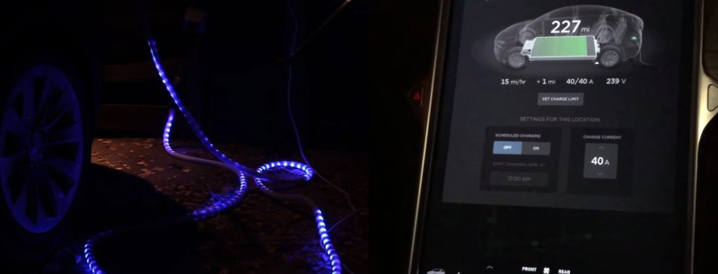
[ch00f] was searching for an idea to build for his father this Christmas, and cast his gaze across those novelty phone charging cables that have “flowing” LEDs along their length. Not one to stick to the small scale, he set out to create a flowing LED effect for a Tesla EV charger.
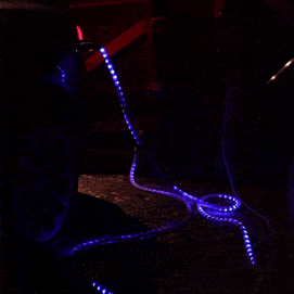 The basic components behind the build are a current transformer, a NeoPixel LED strip, and an ATtiny44 to run the show. But the quality of the build is where [ch00f]’s project really shines. The writeup is top notch — [ch00f] goes to great lengths showing every detail of the build. The project log covers the challenges of finding appropriate wiring & enclosures for the high power AC build, how to interface the current-sense transformer to the microcontroller, and shares [ch00f]’s techniques for testing the fit of components to ensure the best chance of getting the build right the first time. If you’ve ever gotten a breadboarded prototype humming along sweetly, only to suffer as you try to cram all the pieces into a tiny plastic box, you’ll definitely pick something up here.
Perhaps you’d like to check out this teardown of a Tesla Model S battery. Video after the break.


You could do this without the mains breakout – use a GMR sensor (e.g. from NVE), which is more sensitive than a hall sensor for detecting magnetic fields, attatched to the side of the cable. You need to slide it along the cable to find the optimum position due to the twist of the conductors, but it works well for currents above about 1A
Terrible and dangerous PCB layout – it has copper pour over mains side, leaving negligible safety clearances
Thanks for the feedback! I did actually increase the isolation around the high voltage side to 15 mils from 10, though I certainly could have widened it a lot more.
I’d also like to point out that your comment had me reviewing some of my assembly pictures, and I just realized that I mixed up my neutral and live connections, so my fuse is on the neutral line! Fortunately, the cable has not gone into service yet, and I’ll have a chance to fix that.
Hey, I see lots of your projects here and they’re interesting.
But :( this one is not so good with the mains clearance. The rule of thumb for me is 3/10ths inch for 240/250V and I would probably suggest 2/10ths inch for 110/120V as an absolute minimum.
So that’s 300 thou (mils) or 7.62mm for 240/250V and 200 thou (mils) or 5.04mm for 110/120v. This is a minimum so it not the distance between pads, it’s the distance between copper or any conductive parts including the case.
If I am reading the PCB correctly then the ground pour includes the mounting holes as well and probably some of the low voltage side. This is unfortunately, simply not safe.
So if it was built for a family member then it’s time to re-do the board. If it was built for a lawyer or politicisation then keep it as it is and I will subsidise several of them if you get the sales.
Thanks for the help. Im really not sure why I decided to bring the ground plane so close. I’ve done other projects before where I had appropriate clearance. I think I was just in a hurry maybe.
I’ve got a ton of extra parts from this build and now that I’m not on a deadline, I can get new boards fabbed super cheap and mail my dad the replacement.
Thanks again. One of the reasons I like publishing my projects in such detail is because of the feedback I get in comments like yours.
Hey, I don’t know if you’re still checking on this comment thread, but I’m digging through IPC-2221, and I’m wondering where you’re getting such clearances from. I’m finding clearances of 0.4 or 0.8mm according to table 6-1 here: https://ee174-fall15-01.courses.soe.ucsc.edu/system/files/attachments/IPC-2221.pdf
Obviously, I should maximize clearance wherever I can, but I’m curious where your “rule of thumb” came from.
My “Rule of thumb” comes from servicing mains appliances from early phonographs to HD LCD display panels so I have seen the non-virtual ‘reality’ of what actually happens, at what distance.
I spent a lot of time on a tropical area that had high humidity, high temperatures and electrical storms.
So here is what you don’t do! Try this page and enter your 110Vots into the calculator –
http://www.smps.us/pcbtracespacing.html\
– and you get a clearance of 1.15mm (IPC9592) which incidentally is much more than on your PCB.
Now I will tell you what’s wrong with that calculation.
Your mains voltage is 110VAC so it has a DC peek of 155 Volts
Wait … Your mains voltage is 110VAC +/- 15% so the DC peek should be 178 Volts
Wait … that is a non-fault condition and in a fault condition the main voltage can be double the average RMS so your peek is 356 Volts
Wait … with a lightning strike some distance away you can still get peeks of over 1000 Volts
Wait … all of these figures assume that the ionisation voltage of air is better than the PCB but hey FR4 is good
Wait … condensing moisture on a PCB is going to break down at much lower voltages
Wait … the breakdown voltage is even worse if the PCB has no conformal coating
Wait … condensation is also dependent on altitude (atmospheric pressure) and temperature
Wait … even the chemical composition of air and particulate pollution effect the break down voltage
And that is why is a total trap to believe that a calculator is going to give you a magic number from voltage alone.
Experience tells me that trace vaporisations, fires and gaping holes in PCB’s drops rapidly by increased distance between mains voltage traces (and other traces) and after about 5.04mm / 0.2″ clearance you only see a flash over with lightning strikes and the other damage to the equipment from the same lightning strike makes impracticable to repair anyway, irrespective of the mains flashover.
Because imperial has been so common for so long I added 0.1″ because two pads 0.2″ apart don’t have 0.2″ clearance because of the pads themselves.
It may sound like I have exaggerated the need for larger spacings. Barrier strips and terminal blocks for mains voltages have a pitch of 9.5mm to 16mm
One thing I should add is that it was a mistake to lower my suggested clearance for your lower main voltage.
Been there, done that, wrote the firmware: https://youtu.be/T52TadGW0WY
see: http://www.poweraware.com/
It flashes when it is overloaded, goes dark when no load and goes faster the more current pass through it.
It uses twisted EL-Wires and is actually, believe it or not CE and FCC certified ;)
Very neat. Reminds me of the USB charging cables which show a similar behaviour – TechMoan and BigClive had videos on this –
https://www.youtube.com/watch?v=PCZTSvgF4h8
https://www.youtube.com/watch?v=am5aHDytIuc
LEDS so cheap they’re being used in novelty cables. Next up, home wiring with that “flow” look.
Any idea of another kind of translucent/diffusing tubing that could be use for these neopixel strips? Something that could be visually more beautiful, and be used for example in a christmas tree?
It needs to make the sound effects from the Buck Rogers in the 25th Century TV show, from scenes in the Starfighter service bay where they had tubes connected to them with lights like these.
Can’t find any images or videos of such scenes, dagnabit. Of course back then they used white incandescent bulbs inside the translucent, ribbed tubing and likely used some sort of mechanical, motor driven switch to alternate the interleaved strings of lights.
this is really neat!
Great use for an Attiny!,The PCB should be improved!. Attinys are great makin very small projects, and a very convenient way to start using them is with a Digispark board ( http://s.click.aliexpress.com/e/ZJyn2je ), no programmer needed!