We see a lot of traffic on the tips line with projects that cover old ground but do so in an instructive way, giving us insight into the basics of electronics. Sure, commercial versions of this IR-controlled light dimmer have been available for decades. But seeing how one works might just help you design your Next Big Thing.
Like many electronic controls, the previous version of this hack required a connection to a neutral in addition to the hot. This version of the circuit relies on passing a small current through the light bulb the dimmer controls to avoid that extra connection. This design limits application to resistive loads like incandescent bulbs. But it’s still a cool circuit, and [Muris] goes into great detail explaining how it works.
We think the neatest bit is the power supply that actually shorts itself out to turn on the load. A PIC controls a triac connected across the supply by monitoring power line zero-crossing. The PIC controls dimming by delaying the time the triac fires, which trims the peaks off of the AC waveform. The PIC is powered by a large capacitor while the triac is conducting, preventing it from resetting until the circuit can start stealing power again. Pretty clever stuff, and a nice PCB design to boot.
Given the pace of technological and cultural change, it might be that [Muris]’ dimmer is already largely obsolete since it won’t work with CFLs or LEDs. But we can see other applications for non-switched mode transformerless power supplies. And then again, we reported on [Muris]’s original dimmer back in 2009, so the basic design has staying power.


Don’t forget like me 10 years ago… it is low voltage in the circuit for a PIC.. but the potential is another thing.. don’t get yourself electrecuted by this design.
Have done that. Big sparks, burnt parts, no fun. Jenny wrote a good article on working on mains circuitry that’s worth a read if you’re playing with this circuit.
In particular, this is a great use case for an isolation transformer — so that you can only electrocute yourself by touching two wires instead of just one. :)
And if you’re not using a transformer, make sure that your neutral line is actually neutral: 3-prong plugs and correctly wired house electricals. Test “neutral” against the ground prong with a multimeter just to be sure. (If not, the “ground” in the circuit will be at house mains voltage with respect to earth ground.)
Even with all the above, the hot wire in this circuit is still hot relative to the neutral, and a clumsy hand can still get you hurt. Her suggested practice of “power off, attach test leads, hands off, power on, read, repeat” is the right way to go here.
Love,
Your Hackaday Safety Mom.
Oh yikes! I think the “Neutral” wire of your AC socket can be pretty far from ground. As I recall it varies with the balance of the current of the two phases of 120V against the center tap of the transformer on the power pole. If you connect neutral to ground at your socket you may get an interesting and potentially dangerous ground loop.
This trick has been hanging around for decades as explained and are now trashing millions of LED lights. Even if you can make it micro-watts it is cheaper just to leave the LED light on 24/7. One spike from a storm will butt my claim. Senator Barry Goldwater that arch-conservative a
(ham) wanted to ban light dimmers back in the early 70’s. I wish he had. They are the noisiest thing on-grid outside of a import sans filter circuit cheap adapter.
Could this be made to work for LEDs by converting to trailing edge dimming?
Anyone know how to do that? I appreciate it would need a hardware modification, but the micro controller should be able to accurately time where in the waveform it should cut off the power then turn it back on at the zero crossing point.
I’ve seen a few leading edge dimmers now but no trailing edge versions.
Yes but you can’t use a triac for trailing edge anymore because you need to turn it off when current is still flowing. The normal practice is to therefore use either an IGBT or MOSFET arrangement to do the switching where you have full control of exactly when the load is turned on and off.
For trailing edge dimmers a MOSFET can be used with a bridge rectifier to ensure that the MOSFET is correctly biased. See here http://www.electro-tech-online.com/attachments/reverse-phase-circuit-jpg.30610/ for an example.
Oops. Someone tied the grounds together. Be careful.
Thanks for that, most interesting! Could one achive trailing edge dimming using a solid state relay in place of the mosfet part of that circuit? So you’d end up with a micro controller with a zero crossing input driving the solid state relay at around 100hz to switch the load off only for the trailing edge of the sine wave?
Most solid state relays use triacs anyway. They therefore only turn off at zero cross.
Another question is, why would you want to dim LEDs that way? It produces a 100 or 120 Hz stroboscope.
I meant LED bulbs (the ones that are designed to be dimmable with a trailing edge dimmer). I’m not sure how they work, but I can. Inform that they do not pass the 100Hz flicker onto their component LEDs – you’re either, that would be awful.
One would presume they have a rectifier, a capacitor and a constant current regulator.
They’re not dimmable because the capacitor charges up to the peak voltage anyways and the bulb simply draws more current by the regulator. The dimmable versions must be monitoring the duty cycle of the AC waveform and adusting the current drive by that.
And there are LEDs which have no rectifier or filter – just the LEDs themselves as the filter and some sort of peak current limiter. You can find those in the cheap lightbulb imitations that sell for a dollar or two – they do strobe and it’s awful to watch – extra fingers appear in the air when you move your hands etc.
Btw. the capacitor is the part which cooks out and gives the smoke after a few thousand hours in those bulbs, so the claims about 25,000 or 50,000 hour lifecycles are just plain bunk. In ideal conditions with clean sinewave in the open cool air perhaps – but not in a light fixture in a real home with all sorts of switching power supplies sending noise down the wires and over/under voltages and all sorts of random spikes that come down the mains.
CFLs and LED bulbs both blow up every couple years and they both cost a heck of a lot more than a regular halogen bulb – except again the cheap ones which don’t have capacitors in them. Those work, but the light quality is atrocious.
>but not in a light fixture in a real home with all sorts of switching power supplies sending noise down the wires
Sounds like you are using electronics that isn’t FCC certification (or equivalent certification by agencies in other countries). FCC also requires electronics to limit the amount of EMI that is injected back to the power line under Conductive Emission.
http://electronicdesign.com/site-files/electronicdesign.com/files/archive/electronicdesign.com/content/content/73803/73803-fig-4.gif
Often they do :-(
There are (at least ) two main types of dimmable LEDs. Some have a very high sophisticeted SMPS which senses the duty cycle of the input mains voltage and adjust the DC to the LED accordingly. They do not flicker.
The other ones have just a resistor. They use several LED filaments in series, so they have a combined forward voltage around 180 to 210V for 230VAC dimmable LED. So yes often they flicker, especially when dimmed down.
VARILIGHT is making training edge(IGBT) IR dimmers for almost 20 years. 5 years ago the design has been updated to work with most of dimmable LEDs as well. No neutral required, multiway, programmable and supports scenes.
I’ve used the varilight ones and can recommend them, but other than talking IR, is there any way to control these modules from an arduino or esp8266?
“The PIC controls dimming by delaying the time the triac fires, which trims the peaks off of the AC waveform”
It’s not trimming the peaks, it’s reducing the average power supplied to the load by by only passing a portion of each half-cycle. A hair-split maybe, but “trimming peaks” is not what’s going on here.
This circuit shows off a useful technique, for sure. But it is certainly dated… first because incandescent bulbs are being phased out, but also because, as seen in other recent posts on HaD, TV remotes are a pretty dated tool too. A more up-to-date version would be LED-friendly, networked, and would be controlled from your phone or a home-automation computer. (or the cloud if you’re so inclined and you wouldn’t mind some Eastern Bloc youth controlling them for kicks).
Obviously, we’re talking ESP8266 now. [ducks]
This is exactly what I was thinking – trailing edge for LED compatibility and easy to interface to a micro controller of choice (mine would be ESP8266 for home automation use). Someone must have done this by now?
The main problem with using an ESP8266 is that the circuit in the OP draws only a few milliamps at 5V, while the ESP draws a couple of hundred mlliamps at 3v3. This means your “power stealing” phase would have to be quite large, Also I imagine managing an ESP8266 in every light switch in a typical house would get old really fast, and all those connections might put more of a load than the designers intended on the WIFI router.
The only problem with this is that the NEC now requires that dimmers and occupancy sensors or other home automation devices actually use the neutral as this design causes a safety hazard for anyone working in the device being controlled by leaving the line voltage live in the circuit even when it it off.
Could a circuit like this even be listed? My assumption is no.
That only stops some people… Some of the stuff I have seen installed in people’s houses is scary. They are called homeowner specials.
The trouble is, if it’s not pretty, it looks scary regardless of whether it ought to be scary or not.
Case in point: https://hackaday.io/project/3939-j1772-hydra
I believe I’ve crossed all the Ts and dotted all of the Is. I believe that, were I to spend the tens of thousands of dollars it would require, I could get that box UL approved.
You are mixing low voltage and high voltage stuff in that box, so you should use the high voltage rating for your low voltage wires. Not too keen on the exposed insulation of your blue wire on those screw terminals either.
That’s enough for me to stop checking.
Ordinary TRIAC dimmers without µC work like this for decades. But normally they have an extra mechanical power switch. If not, then use the circuit breaker or just don’t touch the contacts of the lightbulb socket. But as explained, they become obsolete anyway with LED lamps.
I have a smart light switch that powers itself parasitically. We’re using it with LED light bulbs on the side of our garage (the smartness is that it knows from the date when dusk and dawn are and adjusts itself). When the lights are off, the LEDs blink briefly once every few seconds.
What I believe is going on is that the parasitic power flow is enough to charge the filter cap after the rectifier in the power supply (I’m guessing it’s a flyback switching supply or something similar). Once the filter cap reaches a threshold voltage the flyback controller starts up, runs a cycle or two to generate output power, which quickly discharges the filter cap and the controller shuts down again. The output power that’s generated is just enough to power the LEDs for a few hundred microseconds – just enough to make a visible blink.
I had this once with a faulty CFL, the EMI suppression choke failed, but it had a parallel 1k resistor. Enough current for “disco-mode”.
Another time I changed something in the wiring of a light circuit and accidently the neutral wire to an LED lamp was not connected at the breaker box. When I switched it on, the stray capacitance of this wire to earth was enough to make the LED lamp strobe quite fast.
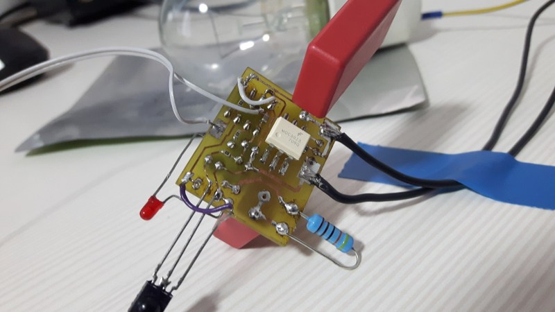
BTW that layout is not recommended. This should go to the what not to do file.
Whoever made that footprint should have routing restrict between the two rows of pins. The opto spacing between the primary side and secondary side is there for isolation. It is not for routing tracking in between. The distance on the left side track and the top right corner pad is too close for line voltage.
This does not matter in this case, as this is no isolated design, it is supplied by a capacitve dropper. The opto is just used as a convenient way to drive the TRIAC. The isolation requirements are only functional isolation, similar to the two main terminals of the TRIAC itself and not safety isolation. In this design exists no “secondary” side.
^ this.
Thanks for the reply. You are absolutely correct. There is no isolation in this circuit, it is all high-voltage.
Most CFL’s wont dim.
Does this still not work with a CFL bulb even if it’s just on/off mode?
What if a high value resistor is put in parallel with the CFL to bypass it on low current demands ? (a resistive load).
Having my lighting controller in serial with the light bulbs (CFL throughout) would be a big help with my wiring. Adding a neutral is a PITA that I might as well convert the house lighting to low voltage DC instead.