
There are certain design guidelines for PCBs that don’t make a lot of sense, and practices that seem excessive and unnecessary. Often these are motivated by the black magic that is RF transmission. This is either an unfortunate and unintended consequence of electronic circuits, or a magical and useful feature of them, and a lot of design time goes into reducing or removing these effects or tuning them.
You’re wondering how important this is for your projects and whether you should worry about unintentional radiated emissions. On the Baddeley scale of importance:
- Pffffft – You’re building a one-off project that uses battery power and a single microcontroller with a few GPIO. Basically all your Arduino projects and around-the-house fun.
- Meh – You’re building a one-off that plugs into a wall or has an intentional radio on board — a run-of-the-mill IoT thingamajig. Or you’re selling a product that is battery powered but doesn’t intentionally transmit anything.
- Yeeeaaaaahhhhhhh – You’re selling a product that is wall powered.
- YES – You’re selling a product that is an intentional transmitter, or has a lot of fast signals, or is manufactured in large volumes.
- SMH – You’re the manufacturer of a neon sign that is taking out all wireless signals within a few blocks.
The Basics
When a signal moves down a wire, there is an electric field created in the space around it. If it’s a DC signal, then the field doesn’t change, so nothing exciting happens in the world of RF, it’s just all constant. Pure DC is very rare. Batteries can do it, unless you’re doing any switching voltage regulation, but anything plugged into wall power is going to have 50 or 60 Hertz sine waves, which then get rectified and transformed and smoothed and poked and prodded into something like a DC voltage. In reality (and depending on the quality of the power supply), this supply will ripple and create small changes in the DC voltage, effectively creating a small changing electric field. Other things, like crystal oscillators, signal lines between chips, and memory buses all have changing voltage signals traveling along a wire from one place to another. Thus, electronics are awash in signals and changing electric fields. It is these changing electric fields, through a lot of math, mostly figured out by Maxwell, Faraday, and Gauss, that results in the electric field becoming electromagnetic radiation.
The frequency of the radiation is the frequency with which the electric fields change, and there are lots of factors that impact that. One is the shape of the wire down which the electric field travels. If you have something called a differential pair, the electric fields going down the wire cancel each other out, resulting in almost no transmission. If you have a wire that doesn’t connect at the other end, then the signal can go down the length and reflect back. If the length of the wire is tuned so that when it reflects it amplifies the wave rather than cancelling, then you have a good antenna. Going back to the frequency, it’s never a perfect sine wave; it’s a combination of waves of different frequencies. An antenna receiver has electronics that will deconstruct those frequencies within a range to extract a signal. Modern stuff is mostly FM, so there’s a main carrier frequency, and it gets modified slightly with the data signal.
Accidental Antennas
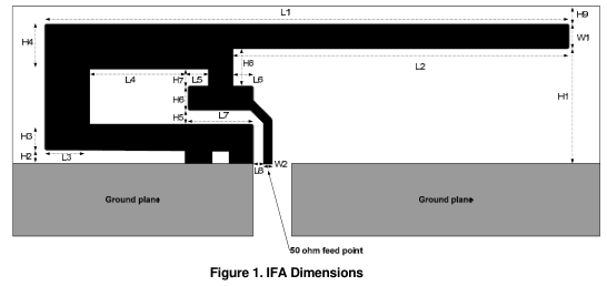
A trace antenna is an antenna made out of a small strip of copper wire on the PCB which just happens to resonate at certain frequencies. This could be intentional, like an F antenna design for 2.4 GHz transceivers, or it could be accidental, like a ground pour that results in a long thin strip. To avoid this, examine your ground pours carefully for any traces that don’t go anywhere. Either eliminate them, or put a via in so that the trace can’t resonate. Keep your ground as blobby as possible. The more fingers you have, and the more you slice and stretch and separate it, the more unintentional radiation you’ll have. As a general rule, don’t have any wires that aren’t connected at both ends unless you are intentionally creating an antenna. This can apply to board IO that isn’t connected. After all, if nothing is plugged in to that IO connector, it’s just a trace that leads to nowhere. If your microcontroller is smart enough to detect when a cable is unplugged, don’t send any signals down that wire. Tie all your unused IOs down to ground.
Via Stitching
A trace that is near the edge of the board and farther from a ground plane layer will radiate more electromagnetic interference. Via stitching refers to putting a ring of vias attached to the ground plane all the way around the edge of the PCB (or as much as possible). You can also line the sides of a signal trace with vias to reduce EMI from the trace. In addition, a healthy dose of vias should connect the ground pour to the ground plane (if you have a separate ground layer on a 4-layer board, or your 2-layer board is mostly ground on the bottom). This prevents accidental antennas, and also ensures that the whole ground stays at the same potential all the time.
Use Decoupling Capacitors and Ferrite Beads
The datasheets for microcontrollers and power regulators have decoupling, or bypass, capacitors connected to the power pins. These chips don’t use the same amount of power constantly; they vary slightly as the chip does its thing, sometimes needing a surge of power briefly. This would look like a rapidly changing signal at the power pins. The purpose of the decoupling cap is to have a small reservoir of power right next to those power pins so that when the chip fluctuates wildly and quickly, the capacitor can smooth out those power demands without propagating that rapid change all across the power traces. The ferrite bead is usually used when connecting a switching power supply to the power plane, as it isolates the noise from the supply, so it is placed (along with a decoupling capacitor) next to the power supply output.
Keep Traces Short
Why would you make a wire any longer than it needs to be? You sometimes need to force a trace to take a pretty circuitous route (heehee) to get from one contact to another. This rule is more about prioritizing which routes get shorter and which can be longer. In general, the faster the signal traveling on the wire, the higher the priority and the shorter the ideal trace length. The crystal should be as close as possible to the microcontroller, with the wires going directly between the two. Every extra millimeter is more changing electric field and more emissions. A UART can have much longer wires because the signal doesn’t change as fast, and the positive voltage rails can meander all over. This is good practice also because faster signals means you want less distance between components to minimize latency, but RF prevention is important, too.
Add IO Filtering
Because your PCB is going to have some cable connections, or board to board connections, or chip to chip connections, each possibly with long traces, you can add some filtering to the traces to reduce their noise by putting resistors in series and a bypass capacitor to ground as close to the noise source (usually the microcontroller) as possible.
Don’t Skimp on the Power Supply
These are super noisy, and the cheaper they are, the more shortcuts are taken. Not only will they blast out RF radiation at harmonics of 50/60 Hz, but the switching power supply, which usually operates at frequencies in the hundreds of KHz is also responsible for a good chunk of noise. Then the output may not be very stable, so that’s a lot of noise traveling down the wire and radiating out, until it gets to your project, which will then be working with noisy power. Not to mention the safety concerns of cheap power supplies.
A Myth
One thing that doesn’t make a difference is angles in traces. It turns out that even beyond 1 GHz speeds, 90-degree angles in traces have no measurable differences over other angles in radiated EMI.
If you want a more thorough application note on PCB layout for reduced emissions, check out TI’s white paper on the topic. Also, see our guide on preparing your product for the FCC.


@Bob Baddeley
Thanks for explaining how you have limited understanding of SAW, harmonics, and or FCC guidelines.
The rest of the article is vaguely accurate anecdotal advice, and does follow what most app note publishers recommend.
“vaguely accurate anecdotal advice” = digestible, for anything more we have to hit the textbooks, like most topics.
Suppose that would be one way to weed out the “haves” and the “have nots”. As if they’re isn’t enough barriers to keeping a publication going, now an IQ test.
Thanks! I aim to please!
can we get the fcc to raid our houses over traces that broadcast?
If they radiate enough, maybe…
Depends, I’ve heard some stories (mainly from around here and that is my basis for this comment),
They would knock on your door and ask you if you are aware of any transmissions.
Then (If you show uncertainty or ignorance) they will (sometimes) help you investigate the source so you can do something about it, i.e. replace and/or repair.
They are usually more helpful than barbaric as they (most of them) know that many causes of interference are unintentional (Malfunctions).
Even one of the links in the article shows this (the neon sign one).
.
Usually in the case of repair, it is best (Cheaper) to find a HAM for testing for interference (assuming they already know how to test and not one of those that just license because they felt like it ) or to recontact your communications council/commission (FCC/OFCOM/ETC..)
It’s ham, not HAM. It’s not an acronym.
HAM, at least these days, usually means hard as a motherfucker. Like going HAM on someone.
It’s true that 90 deg vs. 45 deg corners doesn’t affect EMI much, but at 1 GHz it might be important to maintain consistent impedance for the trace.
Indeed, I was thinking that sub-note should have been added to that sentence. +1
45 degrees still sucks for constant impedance, though. If you’re paying that much attention to corner reflections, you’ll need to model the miter more accurately than just “use 45 degree corners.”
However, the one note I have seen regarding 90 vs 45 degree corners is that 90 degree corners in lower-quality manufacturing processes can cause problems with acid traps, leading to overetching. Even that problem is mitigated mostly nowadays by photo-activated etchant.
I wouldn’t say it sucks- it’s better than 90 degrees, – the corner can be modeled as a capacitor tied to the trace, and it’s *really* small (1pF at 1GHz has a reactance of 160 ohms, and I doubt that the corner adds near to a pF)
Holy crap, 160 ohms would be a disaster. You can see 20 ohms easy (its like 1 dB), which would be like 100 fF.
Huh? You’re going the wrong way- at 1GHz, 100fF is 1600 ohms reactance. I understand that a 1pF cap would be bad news at 1GHz, but there are engineering decisions to be made. Any impedance continuity is bad on a transmission line, but it is relative. At a GHz, without going to extremes in the tolerances of the PCB material, with a reasonable size trace, a 45 degree corner will probably be overwhelmed by the other variables in the system.
Gah, I was stupidly thinking of it in terms of a change in the final impedance of the trace, and totally the wrong way, too. In any case, even 100 fF of excess capacitance can be a problem if the circuit’s tuned, because you’ll shift the frequency away. I’ve regularly trimmed back ground planes under pads in order to compensate for parasitics that small.
However, the “engineering decisions” part is just silly: there’s no reason why PCB design software can’t do an arc rather than a sharp 45, and calculating the correct miter to keep trace width as constant as possible is just math. It’s not an engineering decision to not compensate something like that. It’s just lack of knowledge or time, both of which should be considered a failure in the tools used.
Nice Article, Thanks for sharing.
This very 90’s looking site has a bunch of useful information on reducing EMI: http://www.hottconsultants.com/tips.html
What a great domain name.
He is the authority on EMI, transmission lines, PCB layout rules, etc.
He happens to live in central Jersey.
I’d add: always, ALWAYS, think in terms of loops. As we learn in circuit theory 101, a circuit is a closed loop, from source, through sink, and back to source. That same theory holds in various ways from DC to daylight. To minimize electromagnetic radiation, circuit length at radio frequencies MUST be minimized. That means bypass early and often, but just as important, consider the proximity of the bypass capacitance to the source of the problem: the active device. And not just physical proximity, but electrical. What does the entire loop look like? Is there a clear ground return, particularly on a two-layer board? Is the capacitor physically close to the supply pin? Is there enough activity to warrant further EMI mitigation, like a ferrite bead?
Here’s a fun story from the chamber. I had a client who was failing for spurious emissions at 150 MHz, pretty badly. All of the GPIOs emanating from the microcontroller were “wet”, so it might make sense to attempt EMI mitigation on those lines. Nope. I asked where the Ethernet PHY was (50 MHz and harmonics are frequently related to Ethernet). Sure enough, there was poor termination on the 50 MHz clock line from the PHY to the transceiver.
But here’s the thing: the GPIOs were NOT at fault. There was a confounding factor here. The poor termination of the clock line led to ringing and emphasis of the higher order harmonics. Those harmonics made their way onto the IO ring of the microcontroller.
Which was poorly bypassed.
In order to facilitate rework of the micro, the board designer had backed the bypass caps way out from the micro. It absolutely served the intended purpose, to allow the micro to be easily swapped, but the added series inductance spoiled the benefit of the bypassing at 150 MHz. As a result, the entire IO ring was allowed to be relatively high impedance at 150 MHz, inviting noise injection and emission through any IO connected to the rail.
The mitigation approach was twofold: add some series termination to the Ethernet clock line, and move the microcontroller bypassing closer to the IC. Luckily we were able to effect these changes over the course of our four hour chamber window and see substantial improvement. The changes were folded in to the next board spin, and the product is now compliant.
Sorry, that should read “there was poor termination on the 50 MHz clock line from the PHY to the *microcontroller*.”
This is a fascinating anecdote, as it points out that bypassing which works for the fundamental might miss the harmonics, which isn’t necessarily obvious to noobs!
Could you clarify what you mean by “IO ring”? Does it refer to the menagerie of peripherals and connectors around the microcontroller on the board, or to a structure within the microcontroller’s die? Or something else? (This seems like one of those terms, like “power rail”, that’s so obvious to those in the know that they never explain it, but bewilderingly obscure to newcomers who aren’t quite at that level yet.)
Sorry, too much time spent with silicon designers. The IO ring is, as you guessed, a structure on die. The way the manufacturing process works, all of the IO pads are at the edge of the die, so the circuitry most directly associated with IO literally form a ring around the other processing circuitry. Hence, the IO ring.
Frequently the datasheet will show a simplified drawing of an IO pin, but I’ll describe it briefly here. There’s generally a driver, consisting of a “totem pole” pair of FETs from a dedicated VDDIO supply to VSS, an input buffer, tied to an internal supply, and some ESD management, frequently as simple as a pair of diodes from the IO pin, one to VDDIO and one to VSS.
And this is where the trouble starts. VDDIO must present a low impedance at a broad range of frequencies to VSS, and not just VSS, the VSS most closely associated with the IO circuitry. If that doesn’t happen, noise can couple in to the VDDIO rail, and once it’s there, it can propagate out any of the IO pins.
So how does it get there? A number of ways. The biggest culprit is the IO drivers themselves. Every time one of those drivers switches on and off, it draws current from the VDDIO supply. The higher the impedance of that supply, again *at the point of use* (note that many micros have multiple VDDIO pins, each *must* be bypassed independently), the more voltage ripple will be induced on the supply and the more noise will be coupled.
The secondary mechanism is a bit trickier, and likely what was happening in the above scenario. Remember all those output drivers, input buffers and ESD structures? Well, each has a little parasitic capacitor associated with it. It’s probably small, 1-2pF, but even then, what’s the capacitive reactance at 150 MHz? 500-1000 ohms. That means that you can effectively model that clock input as having a little 500-1k resistor to the supply rail. Again, once that noise is on the supply rail, it’s free to propagate out any of the other IO pins either by virtue of an active high-side driver, or simply through the same parasitic capacitive route that it took onto the supply. The only way to avoid that is to be meticulous about keeping that supply well bypassed.
150MHz, eh?
https://i.stack.imgur.com/v3PEG.gif
Maybe try embedded capacitance materials if bypassing is really that critical to your design.
http://multimedia.3m.com/mws/media/440094O/using-embedded-capacitance-to-improve-electrical-performance.pdf
Also reference this:
http://www.ti.com/lit/ml/slyp173/slyp173.pdf
thanks for referencing those things, it’s good to have a refresher every now and then.
Bypassing is critical to most designs, but it doesn’t need to be difficult, expensive, or intrusive. In most cases 1-2 0402 ceramic caps at 0.1-0.5 cents apiece per supply pin will suffice. The trick is making sure you’re not shooting yourself in the foot. When I’m doing a layout, the first step is to place the actives, followed immediately by bypassing and any EMI or SI critical components (ferrites, termination). When it comes time to route, power and high frequency signals always come first. It’s generally when this approach hasn’t been followed that I get a call, either as the designer (thankfully not recently) or as an EMI consultant.
“I’d add: always, ALWAYS, think in terms of loops.”
Yes. Absolutely. I would say it “remember that current flows in loops. You can see the signal path, but you *have to imagine the return path right underneath it*.”
In higher layer count designs, a lot of times you end up needing multiple ground layers (not isolated grounds, just multiple layers), because if you stack signal layers over a single ground plane, there’ll be crosstalk. In addition, sometimes you’ll need stripline signals or CPWG, and so you’ll have multiple ground layers there.
What gets forgotten often in those situations is that when your signal crosses from a layer with its ground return on *one* plane to a layer with its ground return on a *different* plane, the return current needs a via as well to switch layers. If you don’t have one, well, that layer switch can *completely* screw up the impedance of that trace. It also causes increased EMI from that trace as well, since the signal loop is now over a bigger area than you thought.
This is why the super-fancy-pants layout packages now have return path via specifications, so they automatically get added when routing.
It’s also important to remember that power planes are often returns for signals as well – so you’d do best to avoid traces with heavy switching crossing over different power planes when they’re the adjacent layer. As in, if layer 3 is a power layer, and you’ve got multiple planes there, try to avoid having any traces on layer 4 cross those gaps.
If you *have* to have signals cross there, put a coupling capacitor right by the trace, *coupling the two planes* (e.g. 3.3V -> 5V in the simplest case), sometimes called a ‘plane jumper.’ Avoiding it entirely is better, though.
“What gets forgotten often in those situations is that when your signal crosses from a layer with its ground return on *one* plane to a layer with its ground return on a *different* plane, the return current needs a via as well to switch layers. If you don’t have one, well, that layer switch can *completely* screw up the impedance of that trace. It also causes increased EMI from that trace as well, since the signal loop is now over a bigger area than you thought.”
I had this happen to me, routed a signal from the top layer to the bottom layer on a 4 layer pcb without a bypass capacitor next to it connected to the ground and power plane. To add to the pain I also didn’t account for the signal going across a power plane split… ughhh the current loop for that signal probably looked like spaghetti :’)
I was already familiar with current loops / current return path but after making that mistake the theory became ‘real’ enough that I won’t be making this mistake anytime soon anymore.
Yup, loop area should be the number one, two and three points of the article maybe following up with accidental stub antennas. Most things flow from loop area. Why do we use decoupling capacitors? To provide a low impedance path for the return signal to minimize loop area. Why do we have a solid ground plane with few cuts? To provide a low impedance return path for signals. And on and on. Compared with loop area, the via stitching is an incredibly minor thing.
Yes, the 90 degree emission thing is a myth, but I still make pairs of 45s just because I think it looks nicer.
90 degree bends are more likely to thin out when the PCB is made than 45s, especially on home etched boards.
I’ve seen 90* bends used in a Cisco WiFi card in what looked like a PCB etched “air core” inductor.
Though the bend was more likely something to do with defining the length of the trace to be present in the field performing the inductive coupling than the trailing tracks ability to transmit (if at all, oh and that is my guess so far).
Do you guys not do ESD / EFT testing?
Does IEC 61000-4-2 not apply to your products?
No. Not even a little.
Great article.
My master’s degree taught me a lot, but nothing ever touched on PCB design and that’s proven to be the most critical aspect of my work since graduation. I’ve learned some of these things the hard way, through failed prototype PCBs. I’ve seen via stitching for thermal issues before, but I never thought about it for RF.
> I’ve seen via stitching for thermal issues before, but I never thought about it for RF.
Oh man! Just do an image search for “RF PCB” and look at all those lovely via fences.
Via stitching is generally done to make Co-Planar Waveguides for strip line transmission lines.
The goal for PCB layout is to minimize the circuit loop area.
All traces that are not over a ground plane are antenna structures.
Antenna reciprocity. You generate lots of emi at a particular frequency, you like receive it there too.
The reason you radiate emissions near the edge of the board is due to transmission line effect of generating a signal with field lines at 5x the trace width over a ground plane. You generally want the ground plane to go pretty close to the edge of the PCB, and back off the signal layers if they contain high speed or high transition traces.
When you setup your STM32 for Fast GPIO mode, ask yourself, does this really need to be fast? If the transistion is fast so are its harmonics.
Spot on,
I seen high quality PCB work where any tracks that couldn’t be routed between layers for some reason:
The tracks (esp. LVDS pairs) are kept very close together with blank PCB space of about 1/2″ or 10mm between them and a ground plane.
Usually said PCBs are in a metal enclosure with all non-radio affecting paths near vents and connectors. (Even seen this construction in decent laptops before)
>All traces that are not over a ground plane are antenna structures.
This is a problem since I am usually constrained to a two-layer PCB.
Zero-ohm resistors are your friend! You can get a reel of, say, 1206 0-ohm resistors dirt cheap, and then any time you need traces to cross over, just drop a resistor to do it. Keep in mind that any time you do that, though, you’ll induce some crosstalk between the two signals that cross over, because their return currents run over the same section of the ground plane.
My guess is that it’s best to jump signal over power (or power over signal) rather than signal over signal, because power gets high-frequency decoupled at the IC anyway, so the actual physical connection back to the supply is low-frequency and the return current is spread over the board anyway.
The other thing you can do which is more effort, but actually can be *better*, is a wire jumper (small as possible gauge, so you can make the pad to mount it as small as possible), and *install the wire jumper on the back of the board.* At moderate frequencies, the 2 sides of the ground plane are functionally *different planes* (electrically connected everywhere), so return currents on 1 side of the plane don’t even see return currents on the other side of the plane.
A 0-ohm 1206 on the backside would work too, but it’ll take up more space unless you put the via in the pad, which is usually difficult for construction. The actual space taken up on the ground plane isn’t a super-big deal, so long as you make sure not to run a trace over top of the pad on the ground layer. Just run the trace through the gap between the jumper.
I do 2-layer boards pretty often, and 0-ohm jumpers are totally my friend. Jumpers on the backside are a trick that people look at once and say “Hey, you’re breaking the ground plane” and then you point out no, you’re not – you’re just using the other side of it.
I had never thought of using 0 Ohm resistors as jumpers. Thanks for the advice!
Don’t panic, just keep your loop area small. Just imagine the return signal following as close to the trace as possible, but on the ground plane. For each cut, it has to go out and around. You can reduce the distance by what I think of as cross stitching. Pop your far side trace up to the top for a little bit and then back down. This creates an additional path for the ground plane. If you picture the loop area, you can find a lot of areas where you can mangle your ground plane and not have much consequence, especially underneath ICs. Creating two layer boards with good low inductance ground *and* power planes is a bit of an art form, especially when you have a lot of signals.
Couple of examples:
https://oshpark.com/shared_projects/gYONveQZ
https://oshpark.com/shared_projects/CxpDITfd
Thank you for the advice and examples.
I recently had the job of getting a medical device through radiated and conducted emissions testing.
Regarding power supply conducted emissions: we tried a number of power supplies from major (and not-so-major) manufacturers, all of which claimed to meet conducted emissions limits. Guess what? None of them would pass without an external line filter. Plan on installing one.
The other area of difficulty was a broad peak at around 150 MHz, This turned out to be from a color display which was held in a metal mounting (but not screwed or otherwise attached, because it was a consumer quality display designed to be enclosed in a plastic clamshell housing). It did have a metal housing, but that wasn’t sufficient, we had to use copper tape to bond the display housing to the metal mounting..
RFI testing is fun!!! (because you learn a lot, and when you come back with a “pass”, the boss thinks you’re smart)
We pay a bunch of money to a guy that comes out with all the equipment and antennas to do our CE testing… I want his job. ;)
He just points out where the problems are and does not have to fix them…
Although knowing where to bodge in a 100pf capacitor to “take the edge off”, and squeak under the limits, does make it look like you are a practitioner of the black RF arts. ;)
“Regarding power supply conducted emissions: we tried a number of power supplies from major (and not-so-major) manufacturers, all of which claimed to meet conducted emissions limits. Guess what? None of them would pass without an external line filter. Plan on installing one.”
Check your PCB layout / coupling to earth. If the device passed CFR Title 47 Part 15B then it’s probably something YOU did.
We had similar experiences with sourced powersupply modules from reputable manufacturers. In the end, we got the report from the lab to them that theyr device failed conducted emission tests and they went and redesigned theyr supply to actually meet the specs they announced in the datasheets. And it’s not like we are a customer who buys 100k units per year and they bend over backwards to keep doing business with us. If we buy 1k per year we have a good year already.
When I re-read the fine print on their datasheets, it said something like “when installed in compliant equipment”
Now, you and I know there’s pretty much nothing except the power supply itself that contributes to conducted emissions, but I guess that statement is their “wiggle room”.
Oh, and the supplies were all “medical grade”, meaning they were supposed to conform to IEC 60601-1 leakage requirements, in addition to the emissions. THAT, they did. Silly me. I figured that if they could get the hard stuff right, the emissions would be a cakewalk.
Possible explanation: look at the size of a line filter, then look at the size of a switching supply. There’s no room to fit those filter components in the switching supply…and constant pressure from competitors to make the supplies smaller.
IEC60601 means leakage current requirements are very stringent since the products are cord-connected.
Leakage current is coupled very easily by large value Y capacitors on input AC-DC EMI filters. Other sources are earth grounded heat sinks that capacitively couple noise into the earth conductor.
Note that many power supplies have a Y capacitor between the secondary dc output ground and the primary side common. This is done to shrink the loop area as much as possible so as to not radiate as much EMI.
Not having Y caps, or working without them is difficult for hard-switched (fixed-frequency, non-resonant) supplies. Those types of supplies are arguably more stable, but perhaps thats because they are simply easier to understand and model.
Y caps serve as filter for common mode noise along with the common mode choke
If your method of grounding the power supply to the product enclosure is crap, then good luck with your filtering.
For traces intentionally carrying RF or HF signals, rounded traces are better than angled-off traces, for impedance and reduced ringing of signals. Look at any recent WiFi or even ZigBee stuff and you are likely to find the antenna feeders have rounded traces with flowing curves instead of sharp 90 degree bends. You want to get as much of that signal to the antenna where it can be radiated in the direction(s) you want. Look at impedance matching traces on boards with USB, PCIe or other buses that have differential pairs, you’ll find rounded folds, not 90 degree angles.
The reason for this (according to Johnson, High Speed Digital Design), is that the width of the transmission line increases slightly at a right angle corner. So, keep the trace width constant, and you minimize impedance discontinuities, which cause reflections.
I believe the reason for this is it is easier to calculate the impedance, not that it is better.
You can actually still use right angle traces, you just have to take a cut out of the outside corner to keep the impedance about the same. 2.4GHz is certainly the range where the signal can start seeing such impedance discontinuities. Another trick is to cut holes in the ground plane underneath, this is commonly used under filter caps or series resistors as the pad is significantly wider than the trace.
If your project isn’t an intentional radiator, and you put it in a metal box, the inside can be whatever mess you want, right? Nothings getting out of the box.
So long as your box has no openings on it, or has 100% shielded connectors and cables to the next box. ;)
RF is like water, it will leak out of any seam, or non metal connector.
If only it was that simple.
Noise gets coupled to wireing that passes outside. Plastic switches “leak”, leds are plastic.
Your metal box can be a radiator as well.
> Nothings getting out of the box.
Then what purpose does it serve? If it has no I/O and no UI…. I could imagine this working for a temperature and acceleration datalogger, and not much else!
As soon as you have power inputs, i/o of any kind, switches, indicators, displays, your box is no longer sealed. Keypad matrix scanning can be incredibly noisy, particularly if done with GPIO with no regard for limiting the slew rate of the signals. (Slew rate = how fast the voltage changes = how sharp the edges of the square waves are = how rich in harmonic content the resulting EMI is.)
LED matrix scanning, likewise. The MAX7219 is a popular chip without slew rate limiting, the MAX7221 is identical but adds that feature. Guess which one you want to use if EMI is a concern!
This isn’t just for commercial products, either. If you’re using radio signals yourself, noise from your own gear can be your biggest problem. Because it’s so close, it doesn’t need to be particularly loud to be problematic.
If you have field wiring, it can couple noise you generate in the box and radiate it / conduct it out of the box.
FWIW, I work with VERY loud RF interference in the presence of millivolt (sometimes smaller) signals, and nope, you can’t make a box that tight. You just cannot. Exact figures escape me, but very roughly 60dB is doing pretty well (gaskets, not accidental slot antennas, no corrosion, perfect conductors, coax braid soldered to copper box as it goes though, feed through decoupling ferrites/caps and on and on –
When I’m working with 50kv – various parasitic capacities on the HV line, from the coax to just plain air – tend to be really high Q, and even though the power supply has internal “supposedly resistive” ballast, peak currents in an accidental arc can easily reach kilo-amps – at kilovolts. Eg megawatts. Now here we are a few feet away working with microwatts and trying to get say, accurate gamma spectra, or accurate detected neutron counts….
So, megawatts/microwatts – 10^12 – a bit more than 60dB!
The upshot is that you have to shield both ends, serious power decoupling and everything you can think of, then tinker some till it actually works well enough so you’re not spoofing your own measurements. And BTW, I’ve been doing RF/EMI since oh, around the early ’60s. Knowing the theory cold isn’t all it takes, though that helps – at least when you find your mistake you know why the fix worked ;~}
Since I’m doing “research grade” stuff – which in a way is more lax than “production grade” as it only has to work long enough to get an answer…and often the output of my test rig will fry computers at several meters even when they are not connected to anything – I indeed use arduinos and raspies as what the heck – it’s a low-consequence environment as Eben says, and they’re cheap and easy to replace in case of oops and an EMI event that was bigger than planned.
Note in real life a fusion reactor such as what I’m working with would not need this sensitive instrumentation right at the reactor – this is research! Some things you only need to find out once…then you can make big ones.
The stitching example seems to be similar construction, PCB grade, soldering quality and power-plane layout to the old (1994 to 1999 era) wincor-(Nixdorf/Siemens) products we work on.
Also some of said products use VCC (5 and/or 12v) as their PCB shield, LOL
with sufficient bypassing Vcc is ground as far as AC goes
Why not have Chips with a socket for the external Oscillator, Plenty of space on so many to accommodate this using SMD tapered clamp.
board thickness….
Though nothing stopping them anyway for the sake of connecting two pins to the top. The unused pins have the 10-14pF harmonic/over-oscillate suppression caps on them.
The next problem is the chip gets used in a decent metal-alloy tablet PC: shorting the clock source unless insulated.
Capton tape will only last so long (a year like anything designed to fail?), then the PC just “Dies’.
The average Joe wouldn’t know how to fix it, but we would at least guess to just replace the Kapton tape.
Board thickness is function of stackup design, it’s completely up to the designer what stack up to use.
Because there are more than 1 type of external oscillator, each with a different trade off including size.
Because an oscillator in a socket would be relatively bulky, uses a lot of board area, relatively expensive, less reliable under high vibration or acceleration, and it will add inductance, parasitic capacitance etc.
You neglected to mention shielding… good for you, good for them. good for everybody.
The title is wrong! The best title is: How to doesn’t make an article.
I think you accidentally the whole article.
You *have* to be careful with ferrites! Steve Weir had a great article from DesignCon 2011, but unfortunately it looks like it might be offline. This article from Analog covers it as well, though.
Ferrites, followed by a decoupling capacitor, form a nice LC filter, which is why you use them. But why don’t you use a normal inductor? Because the resonant LC peak would *amplify* signals, not attenuate them, and ferrites are lossy (resistive) at their self-resonant frequency.
Except your cap *moves the LC resonance back into the inductive region!* Which means if you’re not careful, a ferrite bead + LC filter can *amplify* switching noise, not attenuate it!
The solution is to simulate it! You may need to add a dominant pole (a cap + tiny resistor in series, or a crappy electrolytic with a high ESR) to damp out the LC resonance of the ferrite.
Wurth Elektronik’s ferrites are *awesome* for this because they provide a full LT Spice set of simulations for all of their ferrites. So you can very, very quickly determine what the best solution is.
Found the article, looks like a great read;
https://web.archive.org/web/20160913021207/http://ipblox.com/pubs/DesignCon_2011/11-TA3Paper_Weir_color.pdf
Duh, Wayback Machine! The presentation he gave on the ferrite bead part is here, and it’s an easy quick read and explanation as to how to handle them.
I like and I will join
This is a very timely article for me as I am currently taking a course on ammerature radio and pcb designs were discussed at my last class, I seem to recall something about 1/10th the distance of the wavelength of the frequency is required in order for a wire to become a feed line? Anyways nice article don’t listen to the haters thank you for your article.
As a rule of thumb we say that any trace that is longer than 1/10th the distance of the frequency it carries should be treated as a transmission line.
Though typically that’s only used for sine waves, for square waves we tend to look at the rise and fall time.
Analog devices has a whitepaper (MT-097) where they say they multiply the rise time in nanoseconds by two and use the result as the max trace length in inches before recommending to treat it as a transmission line.
All signals degrade if you do not treat them as transmission line but by applying rules of thumb you’ll be fine most of the time..
“..it’s never a perfect sine wave; it’s a combination of waves of different frequencies.”
I think you mean to say it’s never a SINGLE perfect sine wave; it’s a combination of MULTIPLE PERFECT SINE waves of different frequencies”.
It’s also worth noting that inputs (such as ADC pins) can be sources of noise as well. TI microcontrollers are notorious at my work for having this behavior. The ADC clock gets out on the pins, regardless of the MUX selection.
That doesn’t sound right.
Doesn’t the chip have a separate AVDD and AVDSS or VREF+ and VREF- ?
We put together a page on our RF PCB capabilities and put together a simple overview of some generally recommended RF materials and bonding materials to use for various applications and industries including consumer electronics, military/space, and medical.
Check it out here:
https://www.sfcircuits.com/pcb-production-capabilities/rf-pcb