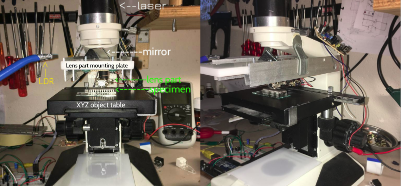
Remember that feeling when you first looked down on a microscope? Now you can re-live it but in slightly different way. [Venkes] came up with a way to make a Laser Scanning Microscope (LSM) with mostly off the shelf components that you probably have sitting around, collecting dust in your garage. He did it using some modified DVD pick-ups, an Arduino Uno, a laser and a LDR.
To be honest, there’s some more stuff involved in the making of the LSM but [Venkes] did a detailed Instructable explaining how everything fits together. You will need a fair dose of patience, it’s not very easy to get the focus right and it’s quite slow, an image takes about half an hour to complete, but it can do 1300x amplification at 65k pixels (256×256). From reading the instructions it seems that you will need a steady hand to assemble it together, some steps look kind of tricky. On the software side, the LSM uses Arduino and Processing. The Arduino part is responsible for the steering of the lens and taking the LDR readings. This information is then sent to Processing which takes care of interpreting the data and translate it to an image.
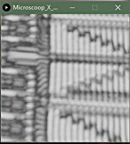
The build difficulty level should be between the DIY Smartphone Microscope and the Laser Sequencer Super Microscope. In the end, if everything goes right, you will end up with some cool images:


This is a nice hack.
If only I had a garage! :/
Right, literally my life goal is to have a nice garage / shop. I hate stuff breaking and knowing it could be repaired if I had a workspace. I manage to do some things here and there but its almost impossible to have a project that lasts for more than a few hours when you have to work in a parking space.
My last car basically fell apart years before it should have because it was impossible to maintain it in a parking lot.
Similarly my current vehicle is in far worse condition than a vehicle of its age should be… :(
Same here. Don’t really care how big the house is, but it will need a garage for all the projects.
I thought of doing this in the 1980’s but the technology wasn’t there. Using the DVD head to steer is clever; I was thinking of piezoelectric discs with mirrors on them. The big advantage of this hack over a conventional microscope is kind of wasted on an IC though; it should have ridiculously huge depth of field. It’s really the thing for images of 3D objects like insects or small crystals.
Looks like the chassis is a gutted Olympus CH .. They make.pretty good platforms for this sort of thing.
Ditch the diode laser and go with a gas laser or other laser that has a TEM00 beam, diodes are multimode and really dont focus that great. An old argon ion laser would be ideal, the shorter wavelength would also give a much smaller spot size.
He started witha dpss green laser which should have been single (transverse) mode, but found that it worked better with a 405nm diode (also single mode, but like you said not as great a beam quality). Judging by the pictures of eeprom cells (about 5um on a side) the limiting factor in his setup is definitely not the ~500nm spot size of the laser beam thats for sure!
It depends on the optics of the DPSS, if he is using a cheap module I would be kind of surprised if it was.
Exactly, the optics are more of an issue here. I can tell you that very high end “materials” LSM’s (reflection mode LSM’s) use 405nm diode lasers. the optical design however is vastly better. Still, I’m impressed! You have no idea how many scientists start with a very good quality widefield microscope, apochromatic objectives and all the information we can give them on how to introduce their lasers in the best possible way and still don’t get results that any better without a lot of effort..
Only the high power diodes are multimode. Below 50 or 100mW you can get many single mode diodes. And of course the shorter the wavelength the smaller the spot. And all this diodes in the optical pickups are MADE for scanning tiny structures (the data pits). Of course a Blu-Ray or HD-DVD diode with 405nm will give the best results. You do not need much power as you do not want to burn the sample.
I don’t understand why people use an LDR for this – they are slow. Why not using the original detection dioes?
Is he moving the Laser beam in both X and Y with the DVD pickup lens? I thought those pickups could only do tracking correction perpendiculat to the disks data track, so only in one direction 0.o
Ohh forget it I just saw what he did. Genius. Although with that level of hacking the advantage of using the prefabricated voice coil over a complete custom build is low.
Anyone interested is designing a 3d-printable part that accepts neodymiums and copper enamel wire to build a 2D or 3D micro positioner?
Hello to you all. Accidently I came on this website and saw my creation here. I am Venkes (Ron Schut), the maker of this thing. I want yo thank you all for your replies!
In your comments, I see that all is not entirely clear. Please visit my instructable page at http://www.instructables.com/id/Laser-Scanning-Microscope/. Here you can see and read (also in the comment section) how and why I did it the way I did it.
One thing I did’nt mention in my instrucrable is the brand of the used microcope chassis. It’s a Novex. Not an Olympus as mentioned by Pez. Although it’s not an Olympus it’s working really fine. In the beginning of my project I did’nt had this chassis at all, and the whole contraption was put together with clamps an magnets, and I used my sons little microscope’s objecttable to focus. It works, but it was not ideal. In my instrucable you can read more about it.
Venkes.