Zero backlash, high “gear” reduction, high torque transparency, silent operation, and low cost. What is this miracle speed reduction technology, you ask? Well, it’s shoelaces and a bunch of 3D printed plastic, at least in [Aaed Musa]’s latest installment in his series on developing his own robot dog.
OK, the shoelaces were only used in the first proof of concept. [Aaed] shortly upgrades to steel cable, and finds out that steel fatigues and snaps after a few hours. He settles on Dyneema DM-20, a flexible yet non-stretching synthetic rope.
Before it’s all over, he got a five-bar linkage plotting with a pencil on the table and a quadriped leg jumping up and down on the table — to failure. All in all, it points to a great future, and we can’t wait to see the dog-bot that’s going to come out of this.
There’s nothing secret about using capstan drives, but we often wonder why we don’t see cable-powered robotics used more in the hacker world. [Aaed] makes the case that it pairs better with 3D printing than gears, where the surface irregularities really bind. If you want to get a jumpstart, the test fixture that he’s using is available on GitHub.
Gearing can make a huge difference to a cyclist, enabling even the least fit rider to climb a steep hill, albeit slowly. [Berm Peak Express] took that to the next level, creating a super-low geared bicycle capable of actually towing seriously heavy loads.
The build consists of a custom 74-tooth sprocket for the rear wheel, paired with a 24-tooth chain ring for the pedals. The custom sprocket doesn’t have any holes drilled or other lightening measures taken, but given the slow speeds involved, the extra rotating mass probably isn’t much of an issue. With that gearing, 3.08 turns of the pedals will result in just one turn of the rear wheel, with the aim to provide tractor-like torque with the trade-off being incredibly low forward speed.
Installing the giant rear cog required using a 3D-printed guide to keep the chain tensioned, and the rear brakes are entirely absent, but it all came together. Bikes aren’t built for towing, and some issues are faced with dragging a Jeep as the bike struggles with balance and traction. However, with some effort, a grown adult can be towed in a child carriage up a hill, no problems.
The bike proves difficult to ride as the forward speed is so slow that balance is problematic. However, it was interesting to see the experiment run, and the wear marks on the hub from the huge loads put through the rear wheel. If you’re digging the weird bikes, though, check out this hubless design as well. Video after the break.
Being able to coast on a bicycle is a feature that is often taken for granted. The use of a freewheel was an improvement made early in the bicycle’s history, for obvious reasons. This also unlocked the ability to build bikes with multiple gears, allowing higher speeds to be easily reached. On a unicycle, however, there’s no chain and the pedals are permanently fixed to the wheel’s axle, meaning that there is (usually) no freewheel and no gearing. [johnybondo] wanted to get some more speed out of his unicycle, though, and realized he could do this with his own homemade internal geared hub for his unicycle.
The internal hub gear was machined and welded by hand as a one-off prototype. There are commercial offerings, but at $1700 it’s almost best to fund your own machine shop. It uses a planet gearset which is more compact than a standard gear, allowing it to fit in the axle. Once all the machining was done, it was time to assemble all of the gears into the hub, lace it to the wheel with spokes, and start pedaling away. Since it was so successful, he plans to build another and lace it to a larger wheel which will allow him to reach even higher speeds. If this isn’t fast enough for you, personally, there are other options available for ludicrous speed.
Now, this gear is still “fixed” in the sense that it’s a permanent gear ratio for his unicycle and it doesn’t allow him to shift gears or coast. There’s no freewheel mechanism so the unicycle can still be pedaled forward and backwards like a traditional unicycle. The advantage of this setup is that the wheel spins 1.5 times for every one revolution of the pedals, allowing him to more easily reach higher speeds.
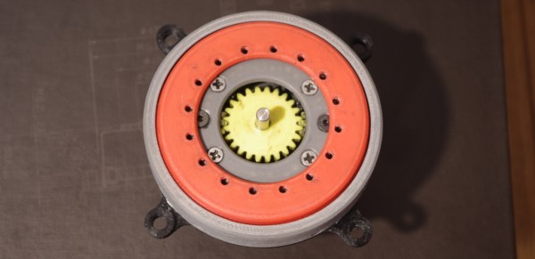
Stepper motors are a staple in all sorts of projects, but it’s often the case that a gearbox is needed, especially for applications like the linear drives in CNC machines and 3D printers. In those mechanisms, a high-torque, low backlash gearbox might be just the thing, and a 3D printable split planetary harmonic drive for the popular NEMA 17 motors would be even better.
Right up front, we’ll say that we’re skeptical that any plastic gearbox can stay as backlash free as [SirekSBurom] claims his creation is. But we can see the benefits of the design, and it has some nice features. First off, of course, is that it’s entirely 3D printed, except for a few screws. That it mates perfectly with a NEMA 17 motor is a really nice feature, too, and with the design up on Thingiverse it shouldn’t be too tough to scale it up and down accordingly. The videos below show you the theory: the stepper drives a sun gear with two planet gears orbiting, each of which engages a fixed ring of 56 teeth, and an output ring of 58 teeth. Each revolution of the planets around the fixed ring rotates the output ring by one tooth, leading to almost 100:1 reduction.
We think the ‘harmonic’ designation on this gearbox is a little of a misnomer, since the defining feature of a harmonic drive seems to be the periodic deformation of a flex spline, as we saw in this 3D-printed strain wave gear. But we see the resemblance to a harmonic drive, and we’ll admit this beastie is a little hard to hang a name tag on. Whatever you call it, it’s pretty cool and could be a handy tool for all kinds of builds.
Practically any combination of motor and gearbox can be mathematically arranged to fit all sorts of problems. You could lift a crane with a pager motor, it just might take a few hundred years. However, figuring out exactly what ratio you need can feel bit backwards the first time you have to do it.
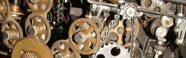
A gear is nothing more than a clever way to make two circles rotate in concert with each other as if they were perfectly joined at their circumferences. Rather than relying on the friction between two rotating disks in contact, the designer instead relies on the strength of a gear tooth as the factor limiting the amount of torque that can be applied to the gear.
Everything is in gearing is neatly proportional. As long as your point of reference is correct, and some other stuff. Uh, it gets easier with practice.
Now as my physics professors taught me to do, let’s skip the semantics and spare ourselves some pedantics. Let us assume that all gears have a constant velocity when you’ve averaged it all out. Sure there is a perceptible difference between a perfect involute and a primitive lantern gear, but for the sake of discussion it doesn’t matter at all. Especially if you’re just going to 3D print the thing. Let’s say that they’re sitting on perfect bearings and friction isn’t a thing unless we make it so. Also we’ll go ahead and make them perfectly aligned, depthed, and toleranced.
Typically, a gearbox is used for two things. You have a smaller torque that you’d like to make into a bigger one or you have one rotational velocity that you’d like to exchange for another. Typically torque is represented with a capital or lowercase Tau (Ττ) and rotational velocity likes to have a lowercase omega (ω). It also doesn’t matter at all; it just makes your equations look cooler.
Now a lot of tutorials like to start with the idea of rolling a smaller circle against a bigger one. If the smaller circle is a third as large as the big one, it will take three rotations of the small circle to make the big one rotate twice. However, it is my opinion that thinking it in terms of the force applied allows a designer to think about the gearing more effectively.
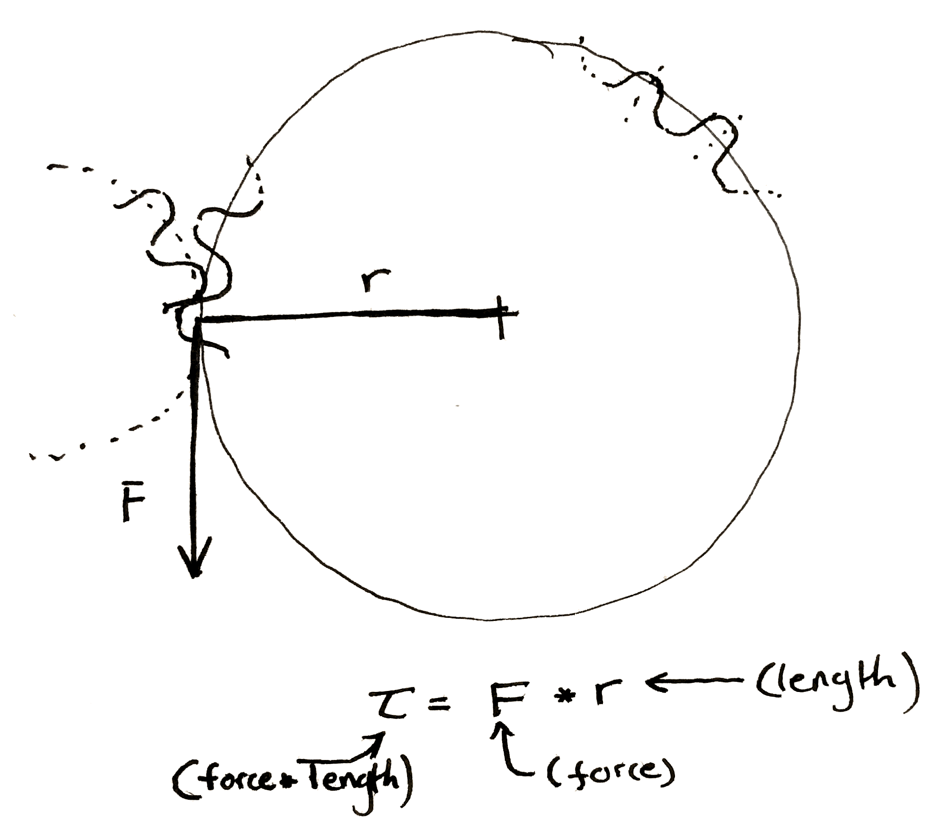
If the friction between the two surfaces of the circle is perfect, then any force applied tangentially to one of the circles will result in a perfectly perpendicular and equal force to the other circle at the point of contact between the two. Midway through writing the preceding sentence I began to understand why textbooks are so abstruse, so I also drew a picture. This results in two equations.
Now, when you have a force perpendicular to the line drawn to describe the radius, the equation for torque becomes really simple.
Multiply the length of the “lever arm”, “radius”, etc. by the force to get the preceding equations. Make sure to include the units.
You should end up force-unit * length-unit. Since I usually work in smaller gears I like to use N * mm. American websites typically use oz-in to rate motors. It is technically ozf-in (ounce-force), but the US customary system has a fetish for obtuseness.
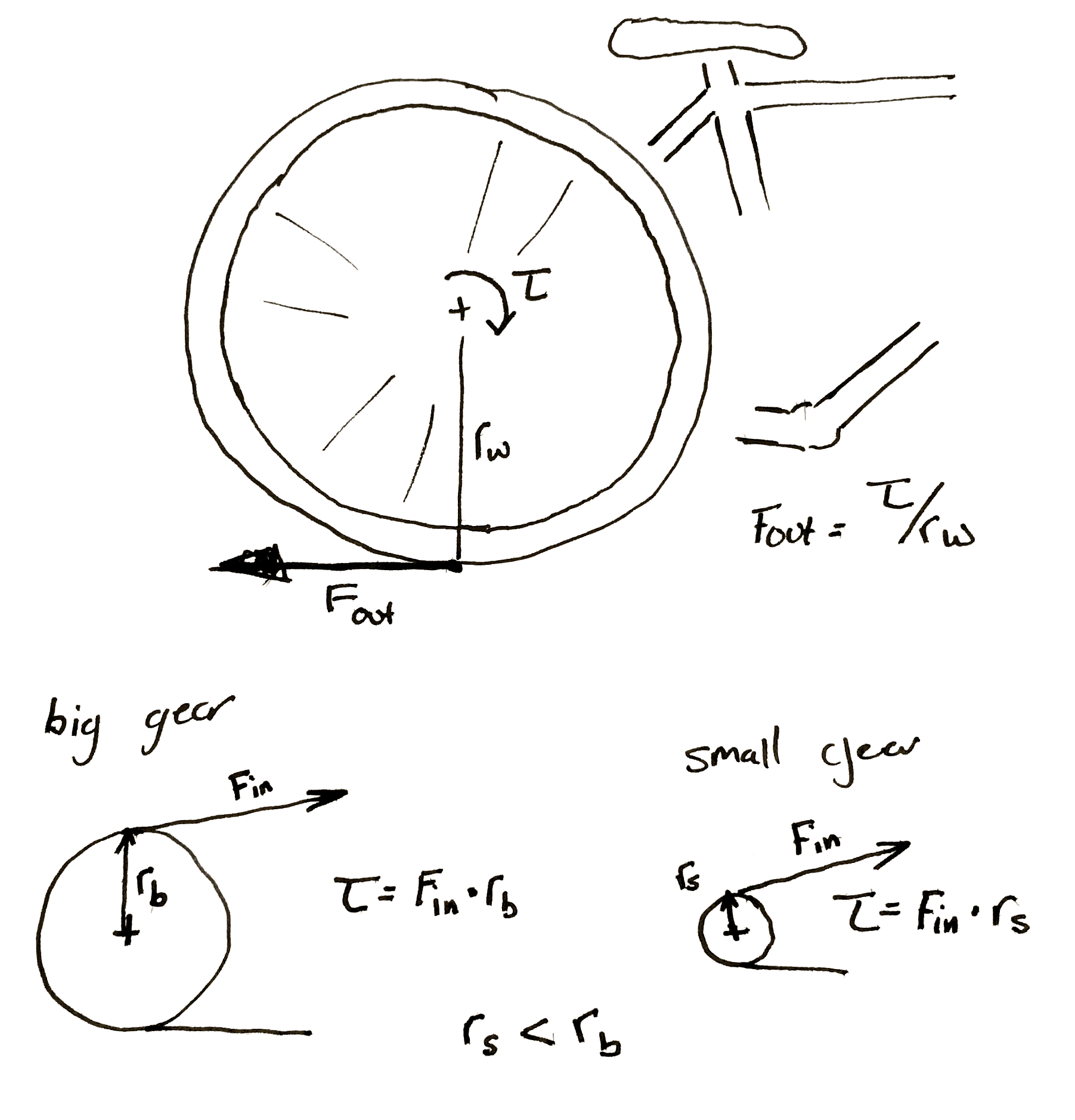
We can make some observations. The smaller gear always sees less torque at its center. This initially seemed a bit counter-intuitive to me. If I’m using a cheater bar to turn a bolt the longer I make the bar the more torque I can put on the bolt. So if I touch the outside of a really large gear I should be seeing a ton of torque at the center of a small gear rotating along with it. However, as we mentioned before, any torque applied on the outside of the larger gear is seen equal and tangential on the smaller. It’s as if you’re touching the outside of the small gear. The torque has to be smaller.
This is why you have to pedal so much harder when the rear sprocket on a bicycle gets smaller. Each time you make the sprocket smaller you shrink the torque input into the wheel. If the perpendicular output where the wheel hits the ground is <input from the small gear> / <radius of the wheel> then it’s obvious why this happens.
Hopefully my diagram doesn’t win a prize for awfulness. Then again, an award is an award. Remember that the bicycle wheel and its input gear are rigidly attached to each other.
It’s also important to note that any time you increase the torque, the speed of the gears slow by the same proportion. If you need 60 N*m out of a motor that can give 20 N*m and you use a 3:1 gearbox to do it. If the motor previously ran at 30 rpm it’s now running at 10 rpm.
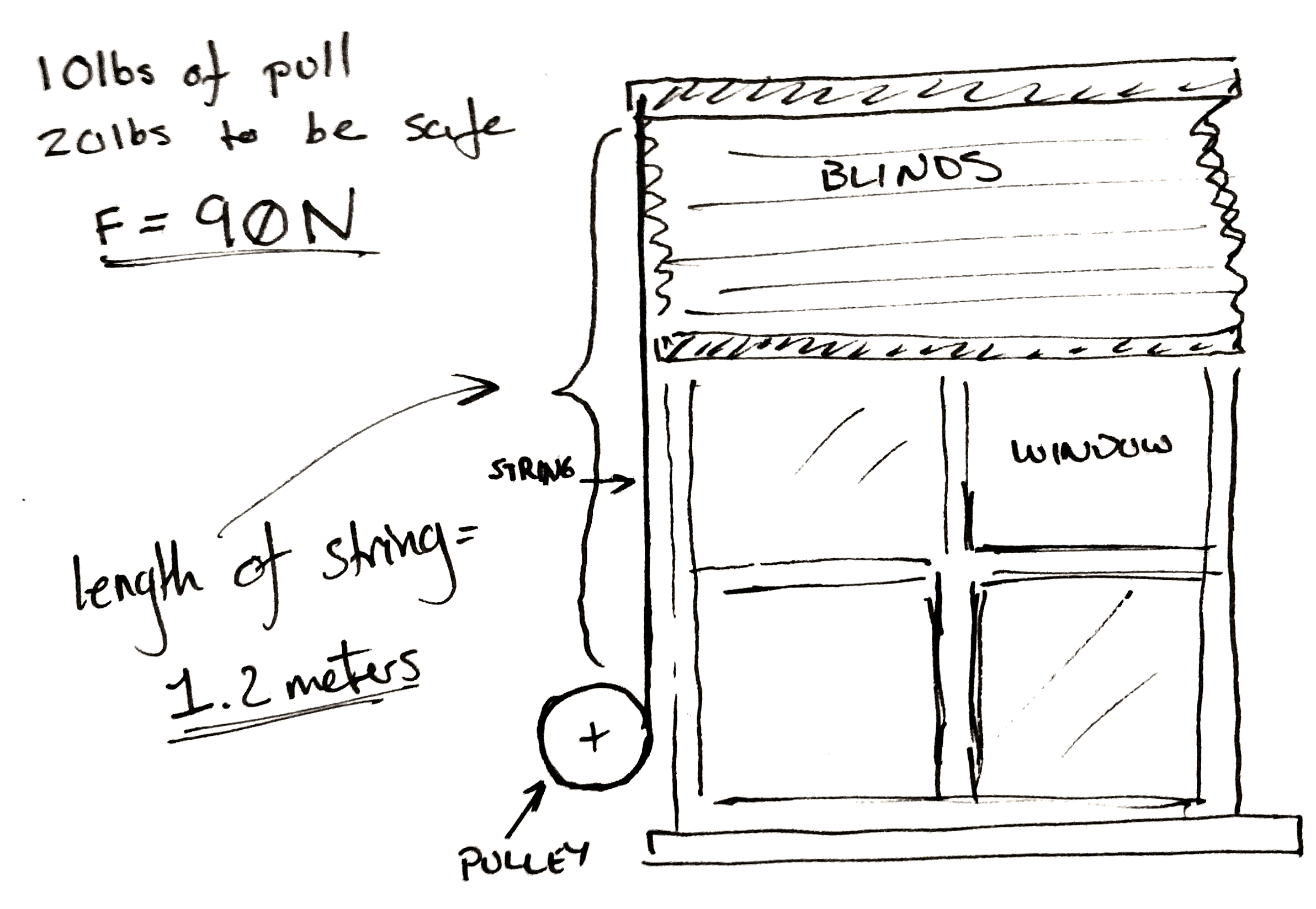
Let’s jump right into an example. Let’s say you want to make a device that automatically lifts your window blinds. You’ve got some junk and a 3D printer.
The problem set-up.
Now you’ve taken a spring scale and pulled until the shutter moves and you know you need 10 lbs. of pull to get the blinds to pull up. To make it easy on yourself you multiply this number by two so you know you need exactly 20 lbs of force to pull the curtain up. Then to make it really easy on yourself convert it all to Newtons. It’s approximately 90 N.
Now you don’t really care how fast the blinds pull up, but you go ahead and pull them up yourself. You get the feeling that the blinds won’t appreciate being lifted faster than the whole range in two seconds. You personally don’t care if takes ten seconds to, but you’d like it not to take too long.
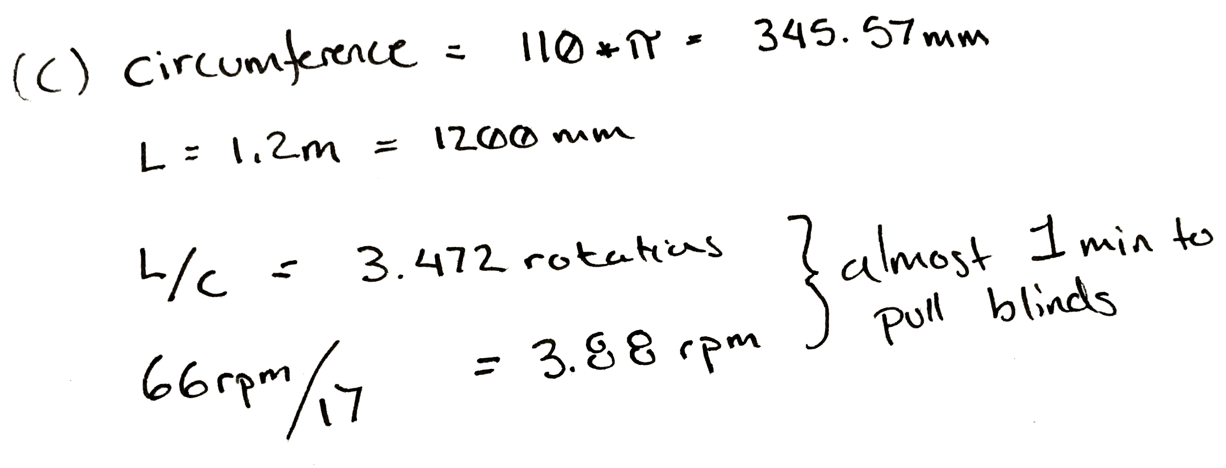
You also measure the length of string pulled out to raise the blinds. It’s 1.2 meters.
A classic.
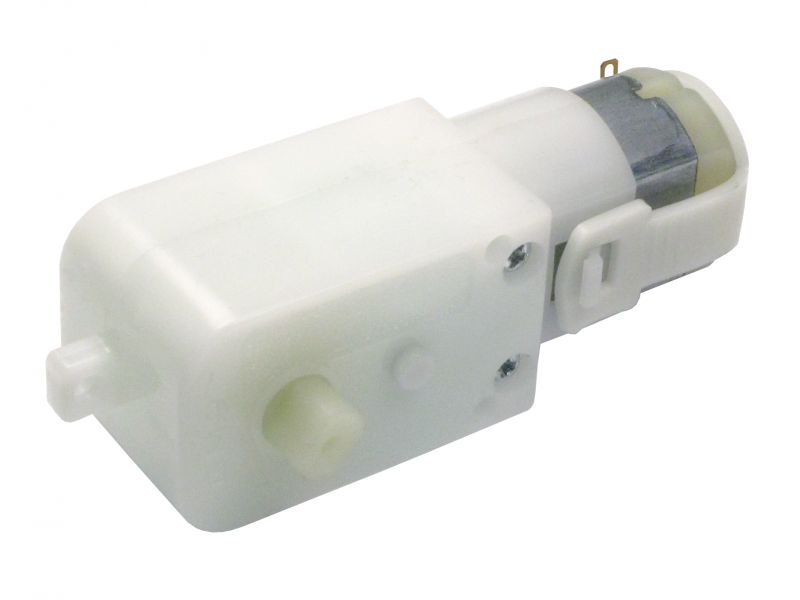
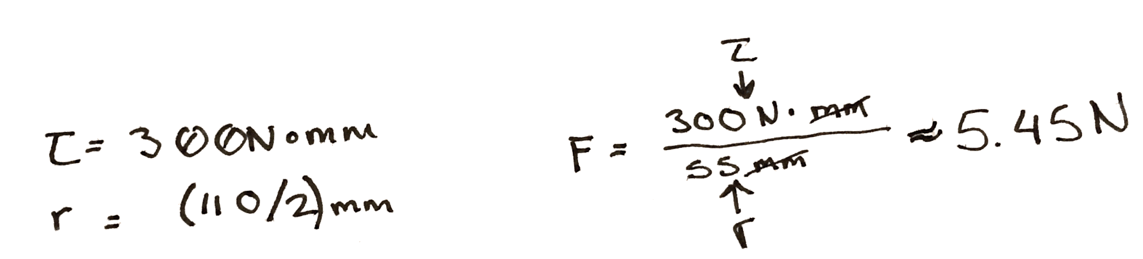
Lastly, you only have one spare power supply and a matching motor left in your entire laboratory after you followed the advice in a Hackaday article. Cursing the day the author was born, you sullenly write down the last specifications. You’ve got one of those cheap GM9 gear motors. 5 V, 66 rpm, and 300 N*mm. You damn him as you think fondly of your mountain of windshield washer motors and 80 lb server rack power supplies that you tossed out.
To start with, you do some experiments with a pulley. You arbitrarily pick, 3D print, and find that a 100 mm in diameter pulley seems to wind it up nicely by hand. By the end of the winding the outside diameter of the string is 110 mm. So you use the torque equations above. You find that at the end of the rotation, if you attach the motor directly, there is only 5.45 N of force being applied to the string. Not nearly enough.
Hrm..
So, since you know everything is more or less proportional, you divide 90 N / 5.45 N, and arrive at an answer of 17. So, at a minimum for every turn of the pulley you need 17 turns of the motor to get the torque needed.
That would be okay, but it messes with our other specification. At a 17:1 ratio, it will take our 66 rpm motor pretty close to a minute to wind the blinds up.
Damn.
This is a moment for some pondering. Make a coffee. Maybe go write a relaxing comment to a Hackaday writer listing their various flaws, perceived and true, in excruciating detail.
What if you wound the string up on a closet rod? Those are only about 30 mm in diameter. You take a bit of rod and wind it up. It seems to work and since it’s wider the string only ends up adding 5 mm to the final diameter. You rework the calculation and find that in this case you only need a ratio of 6! Yes.
Now some of you who have done this before are likely gnashing your teeth, or more likely already down in the comments. Unfortunately it’s all proportional. While you only need a ratio of 6:1 now, nearly a third. You also need to rotate the pulley approximately three times as much to pull the same length of cord.
Sometimes you can’t win. In this case the only solution is to order a new motor. You look online for a bit and realize that one of the 12 V motors you threw away last week would work perfectly for this. You wouldn’t even need a gear box. You could attach it straight to the pulley. You look around your perfectly clean and orderly garage and feel empty.
However, just for fun you build a 6:1 gearbox anyway. It’s a hack after all.
Cover photo of the hilariously complicated Do Nothing Machine credit to the Joe Martin Foundation.