A car is a rolling pile of hundreds of microcontrollers these days — just ask any greybeard mechanic and he’ll start his “carburetor” rant. All of these systems and sub-systems need to talk to each other in an electrically hostile environment, and it’s not an exaggeration to say that miscommunication, or even delayed communication, can have serious consequences. In-car networking is serious business. Mass production of cars makes many of the relevant transceiver ICs cheap for the non-automotive hardware hacker. So why don’t we see more hacker projects that leverage this tremendous resource base?
The backbone of a car’s network is the Controller Area Network (CAN). Hackaday’s own [Eric Evenchick] is a car-hacker extraordinaire, and wrote up most everything you’d want to know about the CAN bus in a multipart series that you’ll definitely want to bookmark for reading later. The engine, brakes, doors, and all instrumentation data goes over (differential) CAN. It’s fast and high reliability. It’s also complicated and a bit expensive to implement.
In the late 1990, many manufacturers had their own proprietary bus protocols running alongside CAN for the non-critical parts of the automotive network: how a door-mounted console speaks to the door-lock driver and window motors, for instance. It isn’t worth cluttering up the main CAN bus with non-critical and local communications like that, so sub-networks were spun off the main CAN. These didn’t need the speed or reliability guarantees of the main network, and for cost reasons they had to be simple to implement. The smallest microcontroller should suffice to roll a window up and down, right?
 In the early 2000s, the Local Interconnect Network (LIN) specification standardized one approach to these sub-networks, focusing on low cost of implementation, medium speed, reconfigurability, and predictable behavior for communication between one master microcontroller and a small number of slaves in a cluster. Cheap, simple, implementable on small microcontrollers, and just right for medium-scale projects? A hacker’s dream! Why are you not using LIN in your multiple-micro projects? Let’s dig in and you can see if any of this is useful for you.
The LIN Protocol
A LIN “cluster”, which is what the local mini-network is called in the jargon, consists of a single master microcontroller and a number of slaves. LIN starts off as standard 8N1 UART serial, usually at 19,200 Baud, and does away with one wire. Next, it adds a protocol that allows this single wire to be used as a bus, shared among multiple slaves. If you tried to roll your own network protocol for simple UART serial communications, you’d end up with something like LIN. Go fetch a copy of the specification (PDF) and read along!
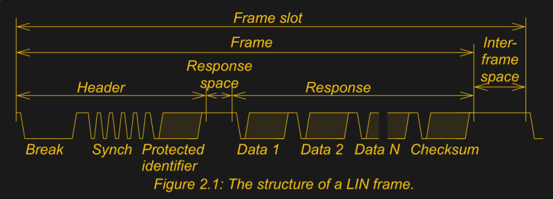
Every LIN transaction is fundamentally the same: the master sends a header that includes a protected identifier (PID), which specifies the task to be carried out. Tasks can be something like “report temperature sensor 2” or “set servo 3 position”. Depending on the task, between one and eight bytes of data follow, with a two-byte checksum. The slaves have to know which tasks to respond to, and how to respond. So if “set servo 3 position” is sent, the servo 3 slave needs to listen for the next bytes and react accordingly. All slaves that don’t respond to the command can ignore data until the next preamble.
 In the case of “report temperature sensor 2”, the slave with the temperature sensor sends its data immediately after receiving the command. Since the byte length is known in advance, and only sensor 2 is allowed to respond to this task, the master knows to listen for exactly, say, four bytes in response and knows how long that should take.
This polling system with the master sending headers and the slaves sending responses guarantees that none of the devices will access the bus at the same time, so LIN gets by with just a single RX/TX line. The preamble includes a sync byte (0x55) that helps the slaves lock on to the master clock, so the slaves can run on cheaper RC clock sources and auto-bauding is possible.
Since the length of messages is known ahead of time, the timing for the master’s polling routine can be written down in a schedule. The master polls the network at defined intervals, and if the slave doesn’t respond within 1.4 times the required time for the transaction, it’s presumed to be missing in action. Either way, the master is on to the next item in its schedule, and won’t retry the potentially defective slave until its turn comes around again. This guarantees a known update rate for all of the devices, which makes life a lot simpler for programming the master.
 Those are the basics. The master sends PIDs, and a series of data bytes follows. Everything’s comfy old UART, call and response, adapted as simply as possible to create a small network.
Extras

Keeping the network that simple requires that the master and slaves all agree on the command set and valid response lengths. That’s a lot of information needed for the LIN cluster to function, in principle. Helping matters out somewhat, there’s a standard format for notating all of this laid out in the LIN spec.
There’s also a standard API for C that both the master and slave microcontrollers can use to make dealing with coding up behavior in a LIN cluster. Combined, this makes a standard workflow for specifying and implementing LIN busses — very handy for the automakers, and not useless for the hacker either.
There is also a sleep state and behavior that’s defined for the bus, with associated sleep and wakeup signals. All of the slaves should respond to the sleep signal, and any of them should automatically go to sleep after a timeout of four seconds if they haven’t heard from the master. Any node, slave or master, can send the wakeup command, and after that the master should go back to its normal polling schedule.
 LIN version 2.0 included a number of optional frame types that make the network more flexible. In particular, “sporadic frames” make the slave’s response optional if it hasn’t gotten any new data since the last update. “Event triggered frames” are like sporadic frames, except they can be additionally responded to by any slave node that has new data.
This introduces the possibility of a collision on the bus, in which case hopefully the checksum doesn’t add up and the master falls back to slave-specific frames as before. These two modes speed up the bus when data updates are infrequent, but add some indeterminacy to the schedule and conditional complexity to the code. Use them only if you need them.
The master can also have multiple schedules, and switch among them. The slaves don’t care — they just listen for the tasks that are relevant to them anyway. There’s no reason for the master to send servo position data every period if it hasn’t changed, for instance, even if it makes things conceptually simpler. Your call.
There is even an optional transport layer spec that is compatible with CAN bus and makes it easier to integrate the local LIN cluster with the bigger network. In short, LIN is a very thoroughly thought through UART bus protocol with decent industry adoption. You’ll find good tutorials from every vendor of LIN transceiver hardware. (Here’s a great intro from National Instruments.)
Hardware — The Physical Layer
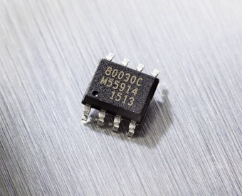
Topping all of this protocol niceness off is a wide variety of LIN transceiver chips ranging from $0.25 to $0.50 for plain transceivers, on up to around a buck or two for “system basis” chips with integrated voltage regulators. These are especially slick, because the transceiver can take care of the sleep/wake logic and turn the power supply to your microcontroller on and off. This makes integrating a slave node that operates at 3.3 V very simple.

Since the LIN bus is designed for automotive, it’s often specced for 12 V because that’s what courses through the veins of your car’s wiring harness. LIN transceiver hardware needs to be able to accommodate even higher voltages, because car electrical systems can be spiky environments. They also have to cope with bus contention, when the transceiver chip may be trying to pull the LIN line down while someone else is trying to pull it up, so there’s overheating protection built in as well. LIN transceivers are robust little beasties.
In contrast to I2C lines, which are pulled up with puny resistors, an automotive LIN bus is pulled up to 12 V with a 1 kΩ resistor. To pull this line down fast enough, LIN transceivers need to be able to conduct tens of milliamps, so they have slightly beefy (for ICs) transistors built in. The combination of a high voltage and relatively high line current means that an automotive-spec LIN bus is good for 40 meters, rather than the couple meters that I2C gives you without resorting to drivers. If you need the distance or the noise immunity, LIN is there for you.
But nothing forces you to run your bus at 12 V, even the transceiver hardware. The Microchip transceivers that I’ve seen run down to 5.5 V, while the ones from NXP and Melexis run down at an Arduino-compatible 5 V.
And nothing forces you to use transceiver hardware at all! You could simply connect a PNP transistor (or P-channel MOSFET) to the bus line and drive that with the UART TX, sampling the bus with the RX line. This has the disadvantage of local echo, but that could be handled in software. Or, with only a few more parts, there’s this solution that we’ve seen before. I couldn’t find any hacker projects implementing LIN transceivers from scratch, though. Maybe that’s because the industrial ones are just so cheap.
Strengths and Weaknesses
No bus is perfect for all occasions, and LIN is no exception. LIN is not particularly fast, being designed around 19,200 baud UART. Updates come fairly infrequently, from a microcontroller’s perspective. A full-length transaction, with timeout, takes around ten milliseconds. If the master polls sixteen devices, that’s an update rate of around seven hertz worst-case. Of course, the master need not poll every device every time, and many times the messages will be half that length, but you’re not going to get more than 200 Hz. On the other hand, the update rate is constant because of the ability to implement tight timeouts for flaky devices, which is great for reliability and simplicity, and it’s not that much slower than I2C.
There are two main versions of LIN that you’ll see in the wild, 1.x and 2.x. In addition to the optional frame types mentioned above, the two versions have different checksum formulas — and the one in 2.x is truly bizarre — necessitating a web-based calculator to make sure you’re doing it right. Instead of addition mod-256, they subtract 255 from any value 256 or greater. It’s like an 8-bit overflow that wraps around to 1 instead of 0. Does this make sense to any of you?
LIN devices aren’t as prevalent outside the automotive industry as I2C or SPI, by a long shot, so you’ve probably never been forced to deal with the protocol. But if you want to network up a small number of microcontroller-based modules, as easily and cheaply as possible, using just one wire (plus ground), it’s hard to imagine anything easier. Writing I2C slave code is certainly no picnic. Writing code to listen for a particular byte on a UART line and then react couldn’t be simpler.
Want to turn your plain-vanilla UART into a bus? Take a page or two out of the LIN book! Have you done so already? Show us!


I love what I can get up to with technology, but how long will it be before your car does a compulsory police detour and you won’t be able to regain control till after the detour (even if you decide you want to change destination)
or how long before you have to pay ransomware before you can drive to work…
a little thought and consideration to what sort of world we are creating and what sort of world we want is in order…
Yes, I share your concerns, but I believe they go beyond the scope of this article. As long as the Master/slave processors are not connected via wireless signals, they don’t provide much of a security hole.
Maybe some “bad guy” could unscrew your taillight lens (though more of them can only be removed through the trunk (boot?)) and access a slave processor, and hijack the network.
By taillight lens[e] I mean that a slave processor would be integrated with the taillight assembly to either operate the lights or report bulb/LED failure.
Already being done, canbus via door mirrors is a thing in some high end cars.
I haven’t read the links yet, but do the master/slaves work at other (higher) automotive voltages?
I’m thinking of BMWs(?) 24 volts…
The one linked in the article is rated to 27V. Trucks use 24V, so it’s reasonably common for automotive stuff to handle it.
27V isn’t enough for a 24V battery system. While charging, the voltage can easily exceed 28V.
FYI , you actually do not need a LIN transceiver for short runs if anybody wants to experiment. A pair of diodes to create the one wire is all that is required as long as your MCU has a LIN capable UART. I develop LIN devices for OEM, and this trick is often used to save cost for on board LIN communication such as comm between a LIN>CAN bridge.
Have you tried putting the UART TX pin into open drain mode as you can do on some micros?
The China OBD dongles also implement LIN/K-line in the cheapest fashion that still works OK?
“Instead of addition mod-256, they subtract 255 from any value 256 or greater. It’s like an 8-bit overflow that wraps around to 1 instead of 0. Does this make sense to any of you?”
Are they they’re trying to avoid a checksum of zero, which would be indistinguishable from a missing checksum?
The new checksum is just using the add-with-carry instruction instead of the add instruction. Not sure what properties they’re trying to get though.
One of the properties is that you calculate a checksum by first adding 32 bit chunks, and then add the two 16 bit halves together, followed by adding the two 8 bit halves of that. And you can do this on both little and big endian machines.
The frame contains only one byte checksum.
Hi,
you wrote “…sampling the bus with the RX line. This has the disadvantage of local echo, but that could be handled in software”.
I am a little confused. Even with a LIN transceiver you will get an echo. That is intended and the software makes use of it to check if there was a transmit error (e.g. by a simultaneus transmit of two devices).
Thanks Elliot! I’m about to start a project using LIN, this article will come in handy.
Retrofitting cars or RVs with LIN using comm over power would have been fun had it not been for the insanely priced driver chips from a certain Israeli company that I wont name…
The checksum method is called end-around-carry. It equalizes the error sensitivity in the high bits versus low bits. Consider that an error in bit 7 of the data using a standard checksum would likely be missed when the sum overflows. For short messages like LIN uses you can calculate this checksum by doing a 16-bit sum and then adding the high and low bytes.