
[Big Fish Motorsports] has a vehicle with an adjustable rear spoiler system that broke in the lead up to a big race. The original builder had since gone AWOL so the considerable talents of [Quinn Dunki] were brought to bear in getting it working again.
Cracking open the black control box of mystery revealed an Arduino, a  ProtoShield and the first major road block: the Arduino remained stubbornly incommunicado despite several different methods of trying to read the source code. Turns out the Arduino’s ATMega324 was configured to be unreadable or simply fried, but an ATMega128 [Quinn] had proved to be a capable replacement. However, without knowing how the ten relays for this spoiler system were configured — and the race day deadline looming ever larger — [Quinn] opted to scrap the original and hack together something of her own design with what she had on hand.
After a mock-up of some fresh code a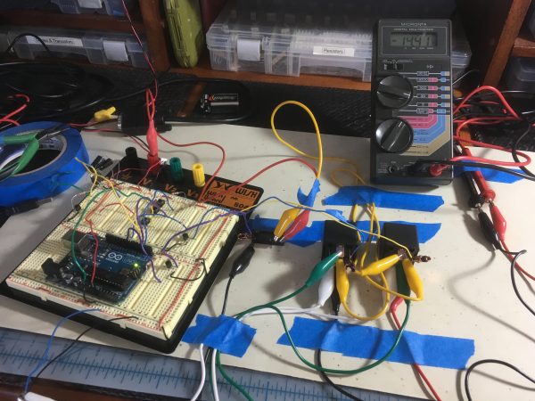 nd testing it without problems, getting stable power to the Arduino was the next major hurdle. Since the car doesn’t provide a nice stable supply — with numerous unpredictable disruptions besides — a 7809 voltage regulator did the trick in protecting the Arduino. But what about the electric motors for the spoiler? Well, a 2N3904 NPN transistor worked in theory — until it blew and was replaced with one of the beefy 160V, 15A transistors that were salvaged from the original circuit. A trio of commonly available — anticipating any race-day breakdowns — SPDT automotive relays drive the spoiler motors and a ‘flywheel’ LED, carefully placed, handles surges once the motors shut off.
So, the spoiler rests in the down configuration and can be raised at the push of a button when the driver feels it’s needed, but what about when braking? Well, [Quinn] was able to piggyback a signal off the brake lights to automatically raise the spoiler whenever the bake is engaged. Awesome!
So after stripping the original ProtoShield to recycle it for her new circuit 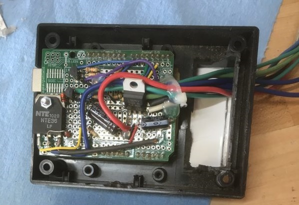 and putting it all together, it worked! Cleaning and closing up the original project box so it would actually protect the electronics this time around, along with proper documentation and automotive diagrams, and this system was ready to be shipped back just in time for the car to be taken off the road due to extenuating circumstances.
Hacking race cars can improve performance — such as we have here — or bring fans closer to the action, but one of our favourite was when we featured a race car that was actually an amphibious race helicopter.


It astounds me that anyone thinks an Arduino and a shield is in any way suitable for something as safety critical as this. I’m assuming AWOL means fired for being an idiot.
Did you see the car? I don’t think they’re going to be on the bleeding edge where the loss of tllt function of their active downforce rear spoiler is going to cause a wreck. It’s not like its a brake system component.
Let’s assume they did some of their homework and set up the aero with the wing in mind. While we’re at it: That’s a wing, not a spoiler. Wings work by having airflow on both sides (bernoulli+deflection, like wings of an airplane) while spoilers work by having airflow on just one side (only deflection, not like wings of an airplane).
So we’re assuming that the downforce in the front has been set up with the rear in mind. The driver hits the track, goes quite fast in a straight, brakes hard before and goes into a turn at fairly high speeds.
Straight => Wing retracted to reduce drag and help with acceleration. See DRS in F1.
Braking => Wing extended to introduce maximum drag and reduce braking distance required. See any recent hypercar, e.g. McLaren P1 or Bugatti Veyron, wing goes almost vertical on those during hard braking.
Turn => Wing extended to keep the rear planted to reduce risk of oversteer.
Now let’s see the possible problems if the wing fails and suddenly does the opposite of what’s expected.
Straight, wing extended => Less acceleration. Not really a safety issue.
Braking, wing retracted => Longer braking distance than expected. Best case is going a bit wide, worst case is going into the railguard.
Turn, wing retracted => Less downforce on the rear. Best case is a slight oversteer, worst case is a full on spin and collision with railguard or other vehicles.
So…how exactly is that not safety related?
The car should still function fine without… I take it the driver would be in-tune with the normal behaviour of the vehicle and be able to take evasive action if the rear wing failed, which is entirely possible for a multitude of reasons other than using an Arduino.
No. The car is a race car. It’s meant to operate on the border of loosing control. The further that border is, the faster the car will be. But also: the better the car warns the driver before going over the edge, the better the driver can feel it coming when he’s about to loose control, and the more time he has to compensate and not crash.
Riding on the edge, that’s what it’s about. And the spoiler helps to push the edge further, but also aids in the feeling for the driver. If the latter is lost, the driver wil go over the edge before he realises. And that’s a safety issue.
Safety? the car doesn’t even appear to have a roll cage, or at least there are no door bars and the doors aren’t even welded shut. Fortunately, the driver does appear to be wearing a helmet and what appears to be some type of racing suit, though we don’t whether it’s a true firesuit made of mutlilayer nomex. If he gets hit by another car in the driver side door area he’s a dead man.
You’re correct, it’s a wing, not a spoiler, but quite frankly, it doesn’t look like a wing you would see on a real race car, that would provide significant downforce. It looks more like those toy wings you see people install on street vehicles to “rice” them up. And the supports for the wing don’t look like they’d be strong enough to support any significant amount of downforce, which is a big hint that this wing isn’t doing a lot.
What leads me to the conclusion, that a fail of the supports is a much higher risk than a fail of the arduino.
I’m not sure what you’re talking about. The door bars are pretty clear to me – I bumped up the contrast so you can see it a little better. http://i.imgur.com/1U8im5Z.jpg
The car itself looks like a LeMons or ChumpCar vehicle (I’d guess ChumpCar personally) and is thusly equipped with a full roll-cage that is required and tested to fit each driver in the car. In fact, they went above and beyond (for LeMons rules anyway) and equipped the car with a HANS device rather than the neck-donut. Here is another picture of their vehicle – http://www.bigfishmotorsports.com/wp-content/uploads/2015/05/slide-1.jpg
As far as the racing suit, those are required to be ‘true firesuits made of multilayer nomex’, and I find it highly unlikely that these two drivers with 15+ years of racing experience ( http://www.bigfishmotorsports.com/our-team/ ) are attempting to skirt the rules in this department.
Additional safety-related things present on the car and pictures – proper fuel jugs, electrical cutoff, hood pins, clean pit area with wall.
While racing is not completely safe (and probably never will be), safety is taken very seriously at these events. This team worked very hard to keep themselves and the people they race with out of unnecessary danger.
Quite. I’d lay good odds that their lap times would be better improved by binning the wing and saving the weight. Not to mention the accoutrements on the front of the bonnet. It can only be for a ‘toy’ race like LeMons mentioned elsewhere.
Well, the end result is also an Arduino with a shield. Also, Arduino boards aren’t as bad so as to not work well with things like these – it’s just a matter of who’s assembling&coding everything.
At the end of the day, it’s just a microcontroller. The hardware is no less safe than the tens that are already in the car.
Depends on microcontroller and buffer build quality. “Buffer” meaning what stands between the board and outside elements/forces. The idea is to use the Arduino for dev purposes and go get the final revision fabbed without all the bells and whistles that aren’t needed, place in an enclosure that keeps everything cool, dry, and shock proof to a certain extent. I’ve seen MegaSquirt boxes that were put in tupperware and hot glued, no grommets, no shock absorbance, just laid under the passenger seat. I also witnessed those break down in ways dev boards should never suffer through as a result…
I have to agree. Cars with air-brakes always reminind me of Le Mans 1955:
https://en.wikipedia.org/wiki/1955_Le_Mans_disaster
But then again, it all depends on the driver. If she keeps the possible shortcomings in mind and uses the extra downforce as an extra, not an requirement, they’ll all be alright.
It’s the human, not the machine.
Safety critical? I don’t think you understand this well enough to comment…
I understand more then you think. I raced for a couple of years – motorbikes rather than cars. If you’re actually racing then you’re right at the limit. Anything that could suddenly affect your handling mid corner could be disastrous. 95% of the time you’d probably get away with it, but not always. I’ve broken plenty of bones when I didn’t. Usually my mistake rather than mechanical failure I must admit.
I’ve also worked on really safety cruel systems – to jam radar guided missiles – a long time ago. That was critical enough to employ 5 team in different locations using entirely different hardware and forbidden from communicating with each other. All 5 went in a rack and voted on the outcome. I don’t believe anyone used an Arduino. ;-)
Greetings, fellow understander. :) ‘Riding on the edge’ is not just a cool term. It really means that you’re riding on the edge. One mistake and you’re over it. And all the modifications to a motorbike or car are there for 3 things:
1. Get more feedback so that the rider can feel how close he/she is to the edge.
2. Make the ‘drop’ less sudden when the rider does go over the edge, so he/she has time for to save it.
3. Push the edge forward as much as possible.
Priority in that order, because confidence without the speed always makes a driver go round the track faster than speed without the confidence.
Points 1 and 2 are all about safety. And only then comes speed.
I know this. With my 1997 900cc Honda Fireblade, I can still keep up with modern 1000cc motorbikes. Because I have the confidence and an ok speed (well, 170mph or 275km/h), while they have huge speed but not the confidence.
So, long story short: it’s safety critical.
But… Why would an Arduino not be good for safety critical things? It’s just an AVR processor. As long as it get good, stable power, and as long as they built in a watchdog timer to quickly reboot if the CPU crashes, and as long as they overdimensioned the relay driver electronics, it should be fine.
Did you follow the link? Don’t think this was a high budget build by any means. The spoiler actuator appears to be an old power window regulator of some sort.
Thinking this is more of a 24 hours of lemons type racing outfit.
I bet for such races you need to squeeze as much as possible
I didn’t know about this 24 Hours of LeMons thing. Thank you, sir.
I HIGHLY approve of this, and must make it a point to go see it some time.
This is an good example of knowing both the practical limitations and the power of ‘good enough’ . And before all else start quoting ISO10605,7637-x,CISPR12, CISPR25, and the automotive ‘functional’ safety crap, this is not a road vehicle. This is a one-time hack for a singular use instance. This is hacker engineering.
Favorite Quinn Dunki quote:
“I think hacking is more than a hobby—it’s kind of a way of life. It’s about shaping your environment to be what you think it should be. It’s about saving things from landfills and giving new life to forgotten or underappreciated artifacts. It’s part creativity, part environmentalism, part self-reliance, and all good times.
It’s fun to talk about stuff you’re doing, but most of my flights of fancy are so obscure or odd that only a select few would find them interesting. The power of the Internet is that it connects all of us oddballs to each other…”
All hail the Might Quinn!
(Thanks for sharing!)
James, I think you have just taken out the best article title for the year.
Flywheel diode, not LED. You can have a pretty significant spike from a relay and could easily fry a diode. I usually use a minimum of a 1N4004 on most relays.
Though I would have abandoned that and just used a mosfet h-bridge to control the motor.
Much as I love overly complex hacks for their own sake…how difficult would a (salvaged) long bowden cable and a long actuator handle (cough “conduit” cough) be? Or even a pushrod/torque tube arrangement. Every single-engine low wing Piper out there drops its flaps that way, so there’s not likely a problem with not having enough force.
Or a simple electro mechanical system that tilts the wing up whenever the brake pedal is pushed? Hit the brakes and the motor quickly runs until it hits a limit switch. Let off the brake and it quickly runs the other way until it hits another limit switch.
Circuits like that are simple, robust, easy to find online, and don’t ever fail due to a microchip dying. Could have the wing lift be brake force proportional by putting the up limit switch on a sprung lever. The harder the car decelerates, that farther the limit switch moves, which makes the motor turn farther. Of course there would be a hard limit for the sprung lever so the setup couldn’t break while braking.
This is about hacking something together quickly without having proper documentation with the things that are at hand.
IOW a proper hack. Most electronics hackers doesn’t have the mechanical supplies needed to make your idea (that may be a good one – but see below) stored beside the electronics supplies.
Doing this without some kind of servo mechanism isn’t likely to succeed for several reasons: the forces involved are large, using mechanical leverage is a dead end as that would make the driver concentrate more on using the lever (or more likely wheel mechanism with gearing due to the forces involved) than driving making the whole thing more of a problem than an advantage.
All together this seems like a much better idea – at least until there are more time to redesign the mechanism/electronics. And hopefully document it. ;)
Megol: “Doing this without some kind of servo mechanism isn’t likely to succeed for several reasons: the forces involved are large, using mechanical leverage is a dead end as that would make the driver concentrate more on using the lever …”
See: https://en.wikipedia.org/wiki/Chaparral_Cars
The 2C was the next car with the innovative in-car adjustable rear wing. The integrated spoiler-wing was designed to lie flat for low drag on the straights and tip up under braking through the corners. This was a direct benefit of the clutchless semi-automatic transmission which kept the driver’s left foot free to operate the wing mechanism.
Best thing I have found to reduce nose and introduce stable power for the arduino is to use a UBEC module for RC cars etc… then isolate both inputs and outputs. no noise and keeps things nice and stable. Then throw in a few fet’s and as long as you slam the gate on and off hard you have minimal heat and stuff just works. :)
the proper title for this article should be repairing something when you have no documentation on it can sometimes be difficult.
One too many relays, should just set up the relays like the original window switch.
Both default to ground when de-energized, then one relay will be up, and the other will be down. If they are both on the result is also the same as both grounded, no movement.
Also, downforce on the rear helps with Oversteer, not understeer. And on a standard street car, front or rear wheel drive doesn’t matter, if your back wheels are lifting it is bad for going fast.
Energizing one relay yields an opposite voltage differential than energizing the other relay. Easy, one output is up, the other output is down.
It would have been cool to see how the 10 relays were wired, for reverse engineering purposes.
Hammers home the need for documentation. I would think the wing would need to mounted much higher to achieve any sort of consistent aerodynamic effectiveness although I could be wrong.
What’s with the paint job? I keep seeing a lot of “race cars” with that style of paint but I never see street cars, even those decked to the gills.
Is it supposed to confuse the driver in the same maligned way the Sacramento Kings hand out noodles to fans sitting behind the basket?
Yes that is the first thing that caught my attention. An ugly paint job.
Maybe they just wanted to have some fun?
looks a littel bit like an erlking-paintjob to me
You see some riced cars with that kind of paint jobs in Europe. It’s also pretty common for car makers to use this kind of camouflage paint when testing their prototypes (not always on private grounds), before they release it to the public.
I’ve heard about that kind of paint on war ships before the RADAR era, where it would make hard to see the shape and the size of the ship, so you’d think twice before attacking it: https://en.wikipedia.org/wiki/Dazzle_camouflage