To a ham radio operator used to “short”-wave antennas with lengths listed in tens of meters, the tiny antennas used in the gigahertz bands barely even register. But if your goal is making radio electronics that’s small enough to swallow, an antenna of a few centimeters is too big. Physics determines plausible antenna sizes, and there’s no way around that, but a large group of researchers and engineers have found a way of side-stepping the problem: resonating a nano-antenna acoustically instead of electromagnetically.
Normal antennas are tuned to some extent to the frequency that you want to pick up. Since the wavelength of a 2.5 GHz electromagnetic wave in free space is 120 cm mm, most practical antennas need a wire in the 12-60 cm mm range to bounce signals back and forth. The trick in the paper is to use a special piezomagnetic material as the antenna. Incoming radio waves get quickly turned into acoustic waves — physical movement in the nano-crystals. Since these sound waves travel a lot slower than the speed of light, they resonate off the walls of the crystal over a much shorter distance. A piezoelectric film layer turns these vibrations back into electrical signals.
Ceramic chip antennas use a similar trick. There, electromagnetic waves are slowed down inside the high-permittivity ceramic. But chip antennas are just slowing down EM waves, whereas the research demonstrated here is converting the EM to sound waves, which travel many orders of magnitude slower. Nice trick.
Granted, significant material science derring-do makes this possible, and you’re not going to be fabricating your own nanoscale piezomagnetic antennas any time soon, but with everything but the antenna getting nano-ified, it’s exciting to think of a future where the antennas can be baked directly into the IC.
Thanks [Ostracus] for the tip in the comments of this post on antenna basics. Via [Science Magazine].


Those measurements should be mm not cm
Yup. 2.4GHz is roughly 12cm, NOT 120cm.
My bad. Fixed. I actually meant .1199 meters, FWIW.
Since the wavelength of a 2.5 GHz electromagnetic wave in free space is 120 cm?? it is 12cm or 120mm !
most practical antennas need a wire in the 12-60 mm range then!
Someone mixed up some dimensions there!
Also the pics are with 60MHz, why is this relevant for 2,5GHz?
Conducting effects are totally different!
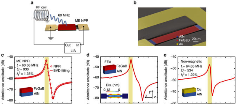
so the accidental typo on units aside (what’s an order of magnitude between friends?), the paper does cover both 60MHz *and* 2.5GHz. While the image was taken from the 60MHz section, I would assume the discussion of the 2.5GHz results are more applicable to things most people have access to (Wifi, etc being around 2.4GHz)
60 MHz is a long waveform. Imagine the size of a 5.8 GHz antenna utilizing this technology. Goodbye external antennas. Hello surface mount chips with integrated antenna structures.
Imagine a child asking what it was like to have external antennas…
Rather, imagine single chips with “passive” carrier-signal based WIFI and MEMS sensors on-die for actual smart dust. At the very least, this technology will play a big role in reducing the cost and difficulty in using RFID systems.
+1, my 1st recipient thereof!!!
You’re welcome, but what I like is that it shows that the field of antennas still has some life in it.
I wonder if you’ll see environmental acoustic effects interrupting the signals.
We’ve built Bulk- and Surface- Acoustic Wave systems before without much outside-world contamination … but evidently not being used as the gain medium for RF.
Gee “at first glance”, this is an interesting paper but I don’t think we’re seeing any kind of “panacea” discovery when it comes to the likes of far-field relatively efficient antenna structures. With other words, the Rules of Thermodynamics still apply. The technique may have broad applications for bi-directional transmission in the near field though.
One thing that raises a red flag in terms of efficiency is as stated “Antenna gain calibration and calculation”:
Assuming that a typical input power of -20 dBm (or 0.01 mW) is needed to completely switch all magnetic dipole moment for radiation, we obtain a radiation power (Pd) to be 2.8×10⁻⁸ W (or
0.28% efficiency).
That’s for transmit as implied in the paper, but the Authors do seem to go to pains to prove the passive transmit/receive reciprocity of the design. So it seems things aren’t looking good for a relatively “sensitive” receive implementation from far-field E-field sources. But near-field E/B-field sources are another matter, but it seems to me that we already have good solutions for this scenario without the added complexity of this near-field approach.
It should also be considered that EM air-gap coupled piezoelectric bi-directional EM to physical-strictive (i.e. “acoustic” as used in the paper) transducer design is very well understood and used in-practice for various applications, sensors in-particular. So the underlying technology (aside from the material-science advances – perhaps) do not seem so new at the fundamental level.
I would like to see better explanation on how the Investigators used the likes of FEM modeling in coming up with the structures tested. This would tell us a lot, especially about the modes of what seems (primarily) B-field coupling to wired E-field conversion. That might provide some insight as to whether what’s being done in this design is more like a slow-wave structure, with structural physical bounds that limit bandwidth or a physical dimensional-strictive sructure.
Once again, my comments are just “first-glance”. But with a short 8-page research paper to work with, the sparse amount of information (so far anyway) may not lead to much more. I will spend more quality time really reading the paper to try and learn more.
One thing I must say is that I THANK the Investigators and their backers for allowing this paper to be released openly – without a paywall to fight with.
+1
Thank you.
+1 as well.
Thanks for the info concerning the performance. It’s really helpful for someone knowledgeable to take the raw numbers and compare them to current antennas.
I’d like to understand more such as what is the acoustic frequency? Is it 1:1 with the electrical frequency? Is it all based on magnetic fields? IIRC from many years ago, these don’t travel as far as electric fields in radio. Is this true?
What kind of bandwidth do these antennas have? I’m hoping we can devise something with a lot of bandwidth that can go with SDRs and I think I remember reading about MEMS potentially being able to solve a problem like this a while ago.
+1 for no paywall thankyou. Most annoying thing in science.
This is an interesting concept but calling it an antenna is perhaps a bit enthusiastic. With a specified gain of -18dBi it certainly is not very efficient. ( for near field transmission / reception this is not necessarily an issue, if the intent is only to transmit a signal from inside the body to a receiver only 10cm away this could be feasible. Maybe the technique would be more widely used as a resonant device for tuning or filtering
Yah, I cut off the antenna on a wifi stick right to the pin of the module and it only seemed to reduce gain down to -9dBi … … which merely reduced local WAPs it could find from about 50 to about 30…. freaking annoying when I was trying to break out of local noise and cantenna my way over a couple of blocks, could not shield the damn thing enough.
“During the receiving process, the magnetic layer of ME antennas senses H-components of EM waves”
But how sensitive is that sensing? Due to the reality of physics I can’t imagine it’s very sensitive, so you’ll need a lot of output on the transmitter, and likely a robust rejection of interference.
Sorry about the negativity though, I’m sure it’s useful and will be very handy in many circumstances and thus might be considered quite the advancement.