The best hardware conference is just a few weeks away. This is the Hackaday Superconference, and it’s two days of talks, an extra day of festivities, soldering irons, and an epic hardware badge. We’ve been working on this badge for a while now, and it’s finally time to share some early details. This is an awesome badge and a great example of how to manufacture electronics on an extremely compressed timetable. This is badgelife, the hardware demoscene of electronic conference badges.
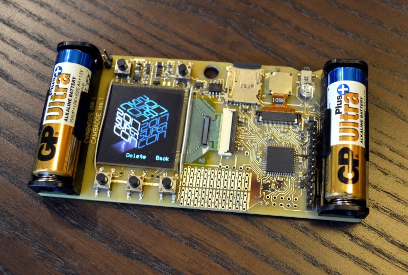
So, what does this badge do? It’s a camera. It has games, and it’s designed by [Mike Harrison] of Mike’s Electric Stuff. He designed and prototyped this badge in a single weekend. On board is a PIC32 microcontroller, an OV9650 camera module, and a bright, crisp 128×128 resolution color OLED display. Tie everything together with a few buttons, and you have a badge that’s really incredible.
So, how do you get one? You’ve got to come to the Hackaday Superconference. This year we’re doing things a bit differently and opening the doors a day early to get the hacker village started with badge hacking topped off by a party that evening and everyone coming to Supercon is invited! This is a badge full of games, puzzles, and video capture and isn’t something to miss. We have less than 30 tickets left so grab your ticket now and read on.


The Beginnings of the Badge
Last year’s Supercon badge, designed by [Voja Antonic], is a beautiful work of art. It has more blinkies than you can shake a stick at, and the capabilities of this badge were amazing; you only need four of them to rickroll the entire conference.
For this year’s badge, we approached [Mike Harrison] of Mike’s Electric Stuff to design a badge. He’s a good friend with the Hackaday crew — he was responsible for giving the Belgrade badge grayscale with gamma correction, and gave a talk about a hot oil and high voltage projector. While x-ray machines and mercury arc rectifiers are more [Mike]’s speed, we were pretty confident he could come up with an interesting idea for a badge.
The initial spec for this badge was a cost of about $30, and a quantity of about 350, for all the attendees of the con. This gave [Mike] a budget of about $10k, and free reign on the design. He came back to us with a few ideas, the first of which was just a bunch of white LEDs driven by a microcontroller. This would be a 24×24 matrix of LEDs, and all the blinkies in the world. This idea was rejected for being a bit too similar to other badges, and the fact that populating huge matrices of LEDs is a pain.
The second idea was a custom segmented LCD. Yes, like a seven- or fourteen-segment LED display, but with the Hackaday logo, with a small matrix for scrolling text or graphics. Building one of these is easy because we have a 3D printer. Building hundreds requires a factory. Looking at Alibaba, the costs and lead times looked viable. This idea was rejected because it’s an all-or-nothing build, and we would only have one shot at getting the display right.
The third idea was best described as ‘some assembly required’. This idea wasn’t fully fleshed out, but this badge would basically be the equivalent of mecanno or snap together plastic model kits. Each con attendee would be given a ‘core’ badge and a few different connectors. These connectors would provide electrical and mechanical links between cores, eventually culminating in a crowd-built Voltron robot during the Superconference.
Sanity prevailed, and we eventually settled on the design for this year’s badge. It would be a camera, relying on exceptionally cheap SPI camera modules available on eBay. Mixed in with a PIC32 that has 64k of RAM and 256k of Flash, a big OLED display, and an SD card socket, and we have a great hardware plan for a conference badge. A little bit of refinement — and the donation of parts from Microchip — adds a serial SRAM to allow the camera to grab QVGA resolution images.
Let’s Single Source From eBay. That’ll Be Great
We have a prototype built, we have most of the BOM on order, and *just* before I wrote this, I hit the fancy green button on the Macrofab website to start the order. Production has now commenced, but I think it’s important to talk about some of the problems that have cropped up already.
The supply chain and BOM management for this badge is pretty easy. Sure, the battery holders are a little weird. (Can someone please tell me what the deal is with battery holders? They’re constantly the most difficult to source component in any project.) The LED we’re using for the camera flash requires a bit of work for assembly, but the majority of the parts are standard, easily sourceable components that have tons of stock everywhere. The camera module and OLED display are not. These came from AliExpress and eBay. There were several suppliers on AliExpress for the display, but the camera modules had only one supplier in the entire world: a single guy on eBay.
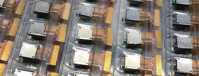
[Mike] specced this OV9650 camera module on eBay. It’s a relatively old camera module, but it does see a lot of use in the Arducam community. It’s 1.3 Megapixels, pretty cheap, and by the time I came onto this project, [Mike] had already figured out all the registers for the camera. The only thing we had to do was buy five hundred of them. Not a problem; the eBay listing said they had already sold hundreds, and they had ‘More than 10 available’. Let’s single-source from eBay. It’ll be great.
After placing the Buy It Now order for eight reels of seventy cameras, the seller got back to me. They only had 35. No, not thirty-five reels of seventy cameras; thirty-five total.
At this point we had a few options. The eBay seller had a few other modules, ‘whose appearance is not the same like the one on eBay’. This module may or may not work with the current version of the badge, so a few samples were quickly dispatched to [Mike] in England. Option two would be to source a similar, compatible camera module from AliExpress. The problem with this plan is the eBay cameras cost about $2 USD. The AliExpress cameras cost $13.50 USD. Considering the BOM for this badge was already at $25, this would blow the budget. It’s a conference badge, and we’d do it anyway, but this would be a terrible choice.
Option three would be to go with another camera module entirely. The OV7670 camera module is plentiful, uses the same FFC connector as the module we’re already using, and if you look at the Arducam library, it doesn’t look like we would lose all our NRE. The downside to this camera is its 640×480 resolution. Not ideal, but it would work.
After a week or two of going back and forth with the eBay seller, sending a few of these sample cameras to [Mike], we eventually had a working solution. The OV9650 cameras ‘with a different appearance’ would work. There was nothing really different about them; the FFC connector was a bit longer, and the lens screw had a slightly different shape. Still, we lost a week of development time single-sourcing from eBay.
Now It’s Your Turn To Hack A Badge
There is no other conference on Earth that does badge hacking quite like the Hackaday Supercon. Need proof? For the 2015 conference, people turned a bit of fiberglass into AM radios, cuckoo clocks, and a rudimentary nervous system. There was even a spark gap, and there would have been a Tesla coil if there was a bit more time. Keep in mind, the 2015 Supercon badge was only a blank PCB.
In 2016, we gave the Supercon attendees a bit more to play with. Last year’s Supercon badge was an array of 128 LEDs, a few buttons, a crypto challenge, and surprisingly little prototyping area. Still, [Zach Fredin] managed to deadbug the badge on a bit of copper clad board. [ThunderSqueak] turned her badge and a few paper plates into a speaker. [Sprite_tm] is an overachiever and managed to rickroll the Supercon audience using four of these badges. There’s no other conference where badge hacking is taken as seriously and the results are as spectacular.
This year will be no different, and we’re giving everyone a head start. We want someone — anyone — to arrive at the con with an expansion board ready to go. We want to see independent ‘shields’ for this badge. This should provide some hints to get your started:
This is it. This is your challenge. We want to see the best badge hacks anywhere, and now it’s time for you to step up. We’re going to be releasing full details including some mechanical drawings and some firmware soon, but the badge is in production and now the ball is in your court. Show us what you got, because this is the best badge we’ve ever done.
Purchase your Hackaday Superconference Ticket now.


I was gonna post my usual question,
“Why can’t these be made available on the HackaDay Store?”
But seeing that what’stheirname donated a bunch of parts, and the main controller is a PIC,
I’ll pass…
basic rule for a badge: One must be able to pin it to shirt without it stretching de weaves.
No mention of a crypto challenge this year?
Firmware is still being done – we still have about 160K flash free – any suggestions welcome!
No USB connector? will people be forced to bring pic kits to program the thing?
Nope, you can load firmware off the SD card.
You gotta get the MPLAB or whatever it is…
You need MPLABX to write new code, but you can load .hex files that others have created from the SD card.
You can have multiple .hex files on the card and select from a menu.
* Sweeps everything off the desk and starts writing a Trojka port *
https://manned.org/trojka/6ab9cab2
===Jac
Nice to see yet another badge this season. For me personally it has the same problem as most other badges: it looks so difficult to get started with.
350 pieces is a nice number and its funny to see the same supply problems we had with 4500 badges for SHA2017. It’s so much more forgiving at 350 and yet it still tends to bite you in the ass when you least expect it.
Love the idea of the camera onboard, it is a bit daring and controversial for us privacy minded hackers. I love it!
Depends what you mean by “get started with”. There are mutiple levels of customisation – for example you can have it show a slideshow of your images or video files without delving into firmware.
It is also very easy to add new application code into the menu structure.
Any chance to share the pin-out of the expansion header now? The conference is only 1 month away and PCBs may have to be ordered.
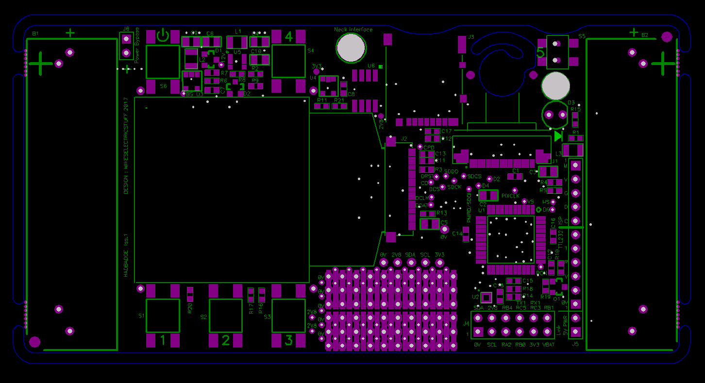
WIll be more docs soon – here’s a sneak peek. I/O is 2.8v. MCU is PIC32MX170F256D.
https://cdn.hackaday.io/images/8911761507719063750.png
BTW the exp header is not populated so up to you what connector you use.
ISP/TTL232 header is fitted.
Sorry I forgot to put a mounting hole to secure a plug-in board!
Does this mean the UART port is 5v tolerant?
No – you should use a 3v3 TTL232 cable. There is a 2k2 series resistor on RXD, so you would probably get away with a 5V cable, though the 2.8v logic levels may be marginal for a 5V cable to receive reliably.
Assuming the badge is being powered from the included AA’s, is there a ballpark estimate for how much current can be reliably/safely sourced from each rail? (2.8v, 3.3v, and 5v)
There is no 5V rail.
2v8 is via a 300mA LDO from 3.3v. Onboard hardware draws 50mA with camera on, +20mA with illuminator LED
3.3v is from an MCP1640B boost reg. Available current will depend a lot on battery state and what is being displayed on the OLED.
I just tried pulling 300mA from 3.3v with fresh Alkaline AAs & it coped, but input current was about 550mA so not recommended for any length of time. At 350mA I was seeing dimming of the OLED (Oled supply is boosted from unregulated battery voltage)
Can’t seem to reply to your last comment about current draw limits
On the expansion header there is a vBatt pin, will it be possible to back power the board through this pin assuming no AA installed?
Yes, but note that if the supply into VBAT is >3.3v, the boost reg will bypass and the 3.3v supply will rise to whatever the supplied voltage is. This is not a problem for the badge (other than the illuminator LED getting very bright) up to 5V, but if you have 3.3v-only stuff, use your own 3.3v regulator ( use the 2v8 rail as on/off detection).
Thanks!
is the camera SPI or something parallel-y? I seem to recall a lot more than 3 or 4 connections to the pic when I looked at the board in Denver.
Ben, better bring the hot air station again!
[great work Mike, badge looks killer!]
It’s not SPI – it’s parallel. Interfaced using PIC;s PMP and DMA.
https://www.youtube.com/watch?v=rQYByorpoFk&t
thanks! OLED is SPI, correct?
yes
Definitely, I’ll bring heaps of smt parts, maybe some stuff to etch boards. Can’t wait to hack on this years badge. Way cool stuff.
It’s not clear WHEN exactly your doors will be open on Friday – I don’t want to spend an hour or two on the street like last time ;)
Hi SHAOS- doors open at noon. See you soon!
Great! :)
My hack? Having some experience mounting those same 128×128 OLED displays, I’d drop the labor-intensive wire tethers (sure, that’s probably a prototype) and use a 1″ square of 3M VHB or equivalent foam tape to stick the display to the PCB. The display is thereby shock-mounted, and won’t come off without great difficulty.
https://www.amazon.com/3M-Scotch-4011-Exterior-Mounting/dp/B00004Z4BV/
The wire is just because it’s a prototype & we might want to take it off. Production will use double-sided tape ( but there will still be the holes for wire)
At first look I thought it had the iPod nano display. Would’ve been nice :D
Didn’t want to us a TFT as you have static power draw from the backlight regardless of what is displayed. With OLED it only draws power for the pixels that are on.
BTW just noticed the article doesn’t mention it has an accelerometer, in case anyone’s started doing a PCB to add one…
I2C addresses 0x60 and 0x32 ( 8-bit) are used onboard.
Curious how you are getting these things made for less than $30, especially that cool OLED. Is there a BOM somewhere? Does macrofab actually handle putting in the OLED or will you do that as a manual step after that? I’m trying to learn because I’d like to design a badge-like thing for a future kickstarter and looking to level up my PCBA skills.
My SD card is obviously loaded since the badge works, but I can’t get W7 to read it.
Never mind. The SD adapter was bad.