With the advent of cheap software defined radios made popular by the RTL-SDR project a few years back, satellite communications are now within the budget of even the most modest hacker. For $20 USD you can get a USB SDR module that is more than capable of receiving signals from any number of geosynchronous satellites, but you’ll need something a little more robust than rabbit ears to pick up a signal broadcast from over 22,000 miles away.
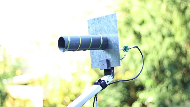
 Building a satellite-capable antenna isn’t necessarily difficult, but does involve a fair bit of arcane black magic and mathematics to do properly; something that can scare away those new to the hobby. But by using a 3D printed mandrel, [Tysonpower] has come up with a feed you can build and mount on a standard dish without having to take a crash course in antenna theory. [Tysonpower] reports the feed has a center frequency 1550 MHz, and works well for reception of Inmarsat, AERO and HRPT signals.
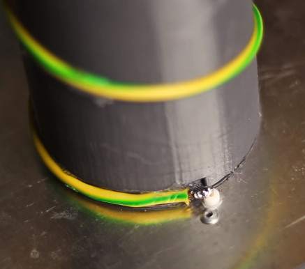
The channel in the 3D printed core of the feed ensures that the inserted wire is of the correct length and in the perfect position for optimal reception. All you need to do is print the core, wrap it with wire, and then solder the end to a connector on a ground-plane that’s nothing more than a sheet of aluminum. [Tysonpower] was even kind enough to model up a mount that will allow you to bolt this feed to a standard satellite dish.
We’ve previously covered using RTL-SDR to receive Inmarsat transmissions, and hardware for the Outernet project, both of which would be great applications for an antenna like this.


Awesome idea! Way to go on this design. I’ve somewhat thought about 3D printing antennas… more from the fractal antenna design influence most recently as well as with microwaves lenses I’ve noted somewhere on HaD. Neato… I just wound my first 2.4Ghz dual helical with house wiring using Andrew McNeil’s templates he has provided on his youtube.com videos describing antennas on this site and others (http://andrew-mcneil.com/). I would provide his YT links, though I can’t access Google, FB or YT sites on this computer.
A spiral conical design with a 3D printed form would be great like in this article regarding the gentleman who made this form and antenna. I even wonder the different materials that could be impregnated or blended uniformly into the polymers to affect the antenna resonant characteristics. Maybe more from an axial design with the blends like ferrite for example for one direction of change.
Way neat, way to go! I think I have a 3D printed item vision and goal now. Time to plan a mission.
McNiel you say? have a look https://www.thingiverse.com/TAz00/designs
Thanks for the links! Way handy… if they’ll download! :-|) Fun (OK, not really) with economies that are not valid causing static, noise, interference and jamming.
That’s certainly a good way to get the right dimensions rather than the approximations when using pvc pipe.
Possibly incorporate a grove to locate the element as well.
What exactly do you mean with Element?
I’m guessing the driver/driving element (the metal part connected to the cable say like the dipole antenna part). With this design I’d say the coil and the back is the ground plane from what I understand.
I am aware of two other elements; the reflector/reflecting (behind the dipole antenna part in a yagi not connected acting like a bar sorta like the ground plane and more as a dish or trough would to reflect the beam) and the director/directing (in front of the dipole antenna part in a yagi not connected to the cable that I think you say sympathetically resonates and steers the beam of resonant energy to the antenna connected to the cable) elements.
There is no other element at a antenna / Feed like this.
It is just the coil that is tuned to the frequency and the Groundplane at the back. That’s it :)
Correct.
There is a groove already ;)
Groovy!
B^)
Way! :-|)
Surely you can just use another tube if it’s the right width, and that you can achieve by getting close with PVC (although 40mm is a standard size in Europe anyway) and finding a simple way to expand it a bit.
As for the groove for the wire, if you put markings along the tube at the required intervals you can easily wind it to match without a groove.
Also the standard copper wire he uses and mentions the outer diameter with insulation of is actually 2.5mm without insulation, just so you know.
You could…but why?
This method allows for a perfect (down to the mm) coil that absolutely anyone can create. Finding the right size PVC and making marks on it to wrap your wire is the exact kind of “black magic” mentioned in the post that keeps people away from amateur radio.
The number of people with access to PVC, a ruler, and a marker greatly exceed the number of people with a 3D printer.
I would argue the number of people with 3D printers greatly exceeds the number of people looking to build a helical satcom feed, so what’s your point?
Make that a plural ‘your’, because the amount of people that seek to make cheap antennas from cheap materials is one that does not immediately overlap with people that throw hundreds at a 3D printer in the hope it finds some use.
Addendum: I see on the third site that turn spacing is 49mm and diameter is 58mm.
And you can get drainage pipes in 60mm, and the site says “The dimensions are not overly critical, but should be within a couple of mm of those quoted.”
The 3rd site also uses silver coated copper of 2mm, unlike the fatter PVC covered copper the first site uses, which I presume is 2.5mm (pure copper).
The copper cable i used has an outer diameter of 3.2mm with insulation and 1.7mm without (pure copper).
Interesting, I assume you are in the EU since you speak German in the video and so would have EU metric standard sizes (of 1.5mm or 2.5mm?), but that sounds more like converted from AWG14. It’s also odd since the insulation is almost as think as the copper then, and that seems a bit much.
Anyway, thanks for giving the exact diameter of the copper since that is the active element and most interesting for those wanting to emulate it. Might be good to update the site too, but it’s not super important I guess since the site for the calculations already mentions 2mm as a guideline.
Yeah I live in germany, I used 2.5mm² “Aderleitung” that has a diameter of 1.7mm without the insulation.
I think you confused mm and mm² :)
A 2,5mm² cable has a diameter of around 1.7mm, 1.5mm² would be 1.4mm diameter.
LOL. I don’t know who submitted my Video to Hack a Day, but thanks anyway :)
If you want this to survive outdoors for any length of time you will want to weatherproof the connection where copper meets aluminum really really well.
I don’t quite know which point on the Feed you mean. The connection of the coil is between the SMA (brass?) and the copper wire. The flange is connected through a rivet with the Groundplane what should be quite weather resistant.
Any reason you used only one rivet? Personally I’d go with at least two, just to avoid the pivot effect causing it to come loose you know.
I used one because i was too lazy to drill a second hole xD
Two rivets or screws would be better of course.
Would have been more useful if he’d designed it using an openSCAD script which would allow easy modification of parameters for the generation of STLs for any frequency. The helical antenna design formula would be integrated into the script and the user would only need to change constants within it for parameters like desired frequency and gain (or, to simplify, just the number of turns). I’d write the script myself if I actually needed a helical antenna.
Good idea but not everybody is so good at such efforts, so why don’t we have someone who is do it instead?