A lot of the DIY laser engravers and cutters we cover here on Hackaday are made with laser diodes salvaged from Blu-ray drives and projectors, which are visible lasers in the 400 – 450nm range (appearing as violet or blue). Unfortunately there is an upper limit in terms of power on visible diode lasers, most builds max out at 5W or so. If you need more power than that, you’ll likely find yourself looking at gas laser cutters like the K40. While the K40 is a great starting point if you’re looking to get into “real” lasers, it’s a very different beast from the homebrew builds using visible lasers.
With a gas laser the beam itself is invisible, making it much more difficult to align or do test runs. One solution is to add a visible laser to the K40 which can be used to verify alignment, but making sure it’s traveling down the same path as the primary laser usually requires an expensive beam combiner. Looking to avoid this cost, [gafu] wanted to see if it was possible to simply move the visible laser into the path of the primary beam mechanically.
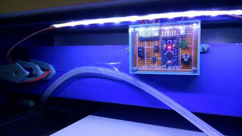
In the setup that [gafu] has come up with, a cheap laser module (the type from a handheld laser pointer) is moved into the path of the primary laser on an arm that’s actuated by a simple hobby servo. To prevent the primary and visible lasers from firing at the same time, an Arduino is used to control the servo given the current state of the K40’s lid. If the lid of the K40 is open, the primary laser is shutoff and the visible laser is rotated into position so the operator can see where the primary laser’s beam would be hitting. Once the lid is closed, the visible laser rotates out of the way and the primary is powered back up.
Running the cutting or engraving job with the lid of the K40 machine open now let’s [gafu] watch a “dry run” of the entire operation with the visible laser before finally committing to blasting the target with the full power beam.
We’ve covered many hacks and modifications for everyone’s favorite entry-level CO2 laser cutter. From replacing the controller to making it bigger, K40 owners certainly seem like a creative bunch.


Clever, but I wonder how exact it is in the main lasers beam path, give it is on a movable mount. More pictures would be nice. I like the idea though.
Linus tech tips had an interesting approach: let the laser burn something. They just put a piece of paper on the mirrors they needed to align, fired the laser for a brief moment, and a black mark appears where the laser hit! Not the safest, but a quick and dirty way of getting the job done. If you need to check where the laser is hitting with any regularity, this approach is almost certainly better. Just need to make sure that the lasers themselves are aligned.
Burning paper on your lens isn’t that wise. But putting paper in the path of the laser to align it is how I learned to align lasers.
It is however a slow process of trail and error, which is slow because you need to close the laser every time for safety.
But, you could combine these methods. Burn 2 pieces of paper in the path of the laser. Then use that paper to align your visible laser, and then adjust the mirrors.
With your suggestion to burn two holes in two different pieces of paper to align the visible laser I can now see this working. Thanks!
I don’t know if that will work because the co2 beam is very wide before the final mirror.
My own experience is that the unfocused beam (of a laser cutter wishfully labeled 40W) is far more than intense enough to burn through paper. That said, I was taught to focus that laser cutter by taping thermal printer paper over a mirror, and then hitting it with a milliseconds-long (software-controlled) burn. It browns the thermal paper without burning it or leaving smoke residue on the mirror.
Of course, if the burn were to be far too long (due to user error or perhaps software glitch), the fragile surface-silvered mirror would be fouled.
it’s the standard procedure used by the expensive pros too : https://www.youtube.com/watch?v=wY5D27TQwZI
Yeah – I tend to stay away from Linus Tech Tips…
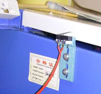
I did this. Battery operated with a tilt switch.
http://rollingpast.com/john/a.jpg
http://rollingpast.com/john/b.jpg
http://rollingpast.com/john/c.jpg
+1! Printable files available?
That’s pretty slick. Looks like a little USB battery providing power? When the lid is closed the metal pieces on the left side push the whole arrangement down and out of the way of the primary laser?
Yes it is one of those 99c USB power dodads with an 18650 in. 3D printed square thing that holds the tilt switch and the laser diode (also off ebay), slides up and down for horizontal/level along with the slider on the welding rod that is pushed by the lid, moving it out of the way. The way it fastens to the laser box is not good. The version shown is on a 550mm laser, for the 700mm laser it is a lot easier as the laser tube is much further back so it doesn’t need to be as long. No files I am afraid, it is years since I did this.
The idea is there, crack openscad into working and spend all of 10 minutes drawing another one. :)
hold on, so if you accidentally lent on that tiny switch, or it failed, or some debris touched it, then the 40W beast would be unleashed? Scary
No, as it’s only an interlock. The software still needs to say “laser on”. (But these interlocks are more commonly done with reed switches instead of mechanical ones)
The beam is not invisible because it’s a gas laser. The beam is invisible because it’s an INFRARED laser. There are visible gas lasers, ya know. Like the ancient helium-neon ones.
CO2 lasers, like the K40, are the cheapest way to make relatively high-power CW lasers. I worked at Los Alamos back in the late 70s when they thought they could use CO2 lasers to achieve fusion. Turns out it won’t work because physics (electrons, specifically).
I remember having a laser pointer that had an attachment that spread the dot into a sharp line. Why not have 2 or 4 of these at 90° intervals around the main laser, angled slightly inward, so that they form a crosshair at the point of aim?
Because they would move with the carriage and not be where the main laser hit except at one point.
It works and it has been done. Two laser pointers are a fair bit of weight to add to the rapidly moving head though.
You could also use a third pointer to add a dambusters-style focus gauge.
Or you know, just buy one with a cross hair lens?
Then it would be off-axis and may not look even. Maybe that’s just a cosmetic issue. I admit I’ve never used a laser cutter and know little about them.
Nice idea, but I’d add an interlock switch to the red laser, to make sure it’s ACTUALLY out of the way before the main laser fired. After all the lid and the visible laser aren’t physically connected
This is very similar to the equipment you’ll see on quarter-million dollar, kilowatt range laser cutters. However, these take the interlock to another level. They switch between the cutting beam and the visible beam using a mechanical shutter device with mirrors on each side. If the shutter is closed, the main beam is redirected towards a water cooled absorber, while the mirror on the other side of the shutter sends the visible beam through the beam path.
And they also use the burning paper – or more often, burning colored acrylic – method of aligning the beam. There’s normally a crosshair device that replaces the mirrors to ensure the beam is centered.
And as always, do not stare into laser beam with your remaining eye.
I run a 2kW laser at work. The way it handles this is issue is it points the HeNe laser at a right angle to the main beam, and a mirrored shutter moves in and out of the beam path. When up, the main beam goes through. When down the HeNe is reflected in the path of the main beam, and the main beam is reflected into a beam dump. (You can run the laser at full power into the beam dump, which is great for calibration).
The HeNe is adjustable to be lined up precisely with the beam, but that isn’t actually as necessary as you would expect. When adjusting mirrors you take it one mirror at a time, and are really only looking at slope error. Once all of the mirrors are aligned to the HeNe, you use a beam reticle (just a tube with a wire plus shape) that sets just past a mirror. You fire the beam through the reticle into a chunk of acrylic (known as a mode burn) and look at how the beam is distributed around the resulting plus shape. Adjust the mirror closest to the laser output to center the plus shape, and your mirrors are aligned. Then you center and focus the nozzle, and finally adjust the HeNe so it points right at your pierce point to give an operator anaccurate idea where the cut will be.
There is a lot of neat stuff on these lasers, such as vacuum pumps that pump down and replace the gas in the resonator every 12 hours, a partially reflective rear mirror that sends a minute amount of laser power into a sensor (full closed loop power control) and some beefy platinum electrodes, that I have luckily never had reason to see outside of the machine.
Our 280MW peak pulsed lasers at work are manually aligned with a long (50x5mm) tube in the beam path and a piece of graphite on the xy table. Move the front optics around until the spot is brightest on the graphite and away you go! Extremely misaligned mirrors present as flashes of light on the edges of the tube
There’s a few alternative designs out there that use LEDs mounted close to the axis of the beam, close enough to be reflected in the mirrors and through the lens. No additional hardware riding on the head.
Hi,
There are some more pictures on my blog http://blog.gafu.de/?p=1579 (in german language)
I have build a little mount with 3 screws springloaded from ballpen springs to align the direction of the visible laser beam.
To set up the position of the laser diode there is a long hole for the srews. Taken these a bit loose make it able to move the baseplate right or left to get to the position the IR beam has.
The second direction, up or down is set with the aligment of the RC servo.
This works nice for month now.
One thing you need to know about aligment in K40 lasers: the thin metalsheet housing disorts easily. So it needs to have a stable base underways, otherwise you lose the laser beam aligment often.