Can you run an electric motor for two years on a single lithium coin cell? [IamWe] figured out how to do it, and even though his donut motor doesn’t look like any motor we’ve ever seen before, it’s a pretty solid lesson in low-current design.
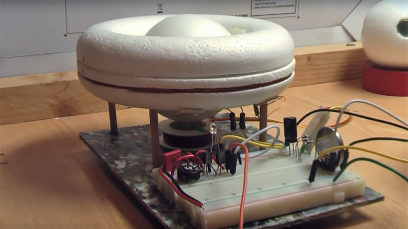
The donut motor is really just a brushless DC motor with a sign-pole stator and a multi-pole rotor. The frame of the motor is built from a styrofoam donut, hence the motor’s name. The rotor is a styrofoam sphere with neodymium magnets embedded around its equator. A sharpened bicycle spoke serves as an axle, and clever magnetic bearings provide near-zero friction rotation. The stator coil comes from an old solenoid and is driven by a very simple two-transistor oscillator. [IamWe]’s calculations show that the single CR2032 coin cell should power this motor for over two years. This one looks easy enough to whip up that it might make a nice project for a long winter’s night. Watch it spin in the video below.
This one seems like a perfect entry for the Coin Cell Challenge contest. Sure, it may not be a coin cell jump starter for your car, but our guess is this motor will still be spinning in 2020, and that’s no mean feat.


This is not what I was expecting, mainly because it rotates in a way I didn’t even consider, and the magnetic bearing is a very nice touch.
Indeed, never presum.
Poles reversed?
Hm. Somehow I’ve got the impression that the battery poles in the schematic (“The Drawing”) are the wrong way ’round. Or there is deeper electronic magic at work which I don’t understand (there *are* lots of electronic magic I don’t understand, mind you).
Some electronic buff around cares to explain?
Which magnets? Rotor or bearing? In either case I think they would work with either polarity, as long as they all faced the same way. The bearing magnets are both attracting the non-magnetized axle and the rotor magnets are either attracting or repelling the stator coil in pulses. Or do I have it wrong? I’d love to hear more about how this works.
Not the magnets. The battery, in the circuit schematics. I mean, – going to the npn’s collector, as + going to the pnp’s collector looks… strange.
Up to now, I have only seen that in an avalanche-based noise generator.
Oh, got it. Silly me. Yeah, I’d like to see some elaboration on the coil driving circuit as well!
This is a super clever design that I’ve definitely never seen before. Great job, perfect motor for the application.
I wonder if efficiency would be better with another stator coil on the other side of the torus. If the rotor has an even number of equidistant magnets, then two coils 180° apart should pulse at the same time and share the same timing circuitry. I’m picturing two coils in parallel with the same number of windings. Or should they have more windings to match the impedance? How would this work best?
My thinking is that this way the forces on the rotor would be more balanced, with more energy going into rotating the stator instead of the coil’s attraction or repulsion trying to move the rotor off its magnetic bearings. Might be able to reduce the current on the coils. Or would the additional heat losses not be worth it? More efficient or less efficient?
Schematic is wrong
Nothing wrong with the schematic. This is one of the very few times you’ll see a functional circuit using bipolar transistors wired in a low beta configuration ( yes, Virginia, sometimes you CAN swap emiiter and collector to make something work).
Question is, why? The beta of a reversed transistor is assumed to be 1, so you need to pass very large base currents to get anything to happen – so what’s the advantage?
I wonder about using germanium semis.
If someone wanted really smooth operation but didn’t need much torque could they build a BLDC where the number of poles on the two parts were coprime and relatively large (say 5 and 7) to give the maximum number of unique phases?
And the practical application of an ultra low torque motor is….?
Because we can.
In that case, whoopy do, a quartz clock does much the same.
My word, some people are so critical. It’s clever, it’s a hack, thus it’s a big thumbs-up. Besides, look at quartz movements with a period of less than a second (“smooth sweep” movements): battery life is significantly less than the standard one-second period movements. So I say “Huzzah!”, IamWe! Great hack!
It’s only missing being placed in a low vacuum bell jar to reduce air friction as it spins!
A mechanical photointerrupter would have its uses in photography or maybe a self contained battery powered gyroscope without external wires to complicate the design.
I have a project where I’m thinking of using a diy disco ball to reflect light around inside of a plastic case to replace a bunch of led strips. It doesn’t need to be low current, but it certainly wouldn’t need torque.
Is that easier, or cheaper, than using LED strips?
A clock motor would run for about as long, the only difference is the physical topology and drive method. Neat project still. Could be used for display effects.
There’s a trick being employed here, the rotator is being suspended by the magnet below it. Once rotation begins, it will spin anyway. I would like a better description of the circuit, it seems to be using negative feedback, but it needs to be described so people can understand it.
No, no! The trick is that the heat rising from the burning transistors spin the rotor.
Ob. :-)
For anyone wanting to copy the build, the creator [IamWe] did credit his sources, so you can see the correct circuit diagram in [LidMotor]’s video at https://youtu.be/kaKYKtg___8
I think the current measurement might be incorrect due the fact that the LED is “powering” the circuit
I love that magnetic bearing design!
wait for it..
The load attached to the motor determines the majority of the current consumption. Most motors are over 90% efficient, so this is a non story.
Have you ever seen this before? Powered by a coin cell? Submitted to a had challenge?
It definitely IS a story.