Cantennas outperform every consumer-grade Wi-Fi antenna I’ve had the bad luck of purchasing. Cantenna is a mashup of ‘can’ and ‘antenna’ creating the nickname for a directional waveguide antenna built from re-purposed steel cans. For anyone who has yet to build one, it makes an excellent afternoon project. Here are some build instructions and technical details. I went beyond that, and ended up catching a rogue WiFi access point in the process.
When I needed to extend the range of some ESP8266-based sensors, cantennas were right at the top of my list of things to try. It was easy enough to build one, attach it to a Wemos Mini D1 Pro, and call the job done… leaving me with plenty of time to over-engineer it, and I ended up down a bit of a rabbit hole.
The first thing I did was stop using cans. Canned goods are not only expensive in my corner of the world, but more importantly don’t lend themselves that well to making a standardized antenna in volume. I can also only eat so many beans! The latter reason alone is enough to consider an alternative design like a modular dish reflector.
Building a Better Cantenna: Ditch the Cans
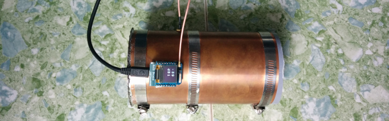
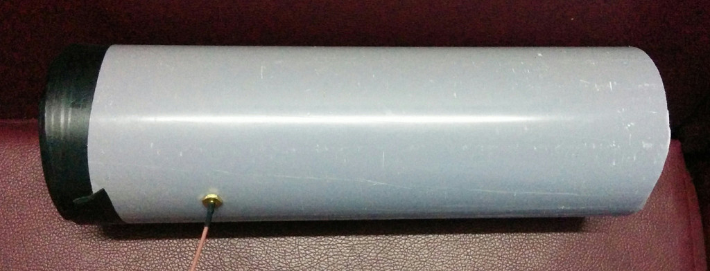
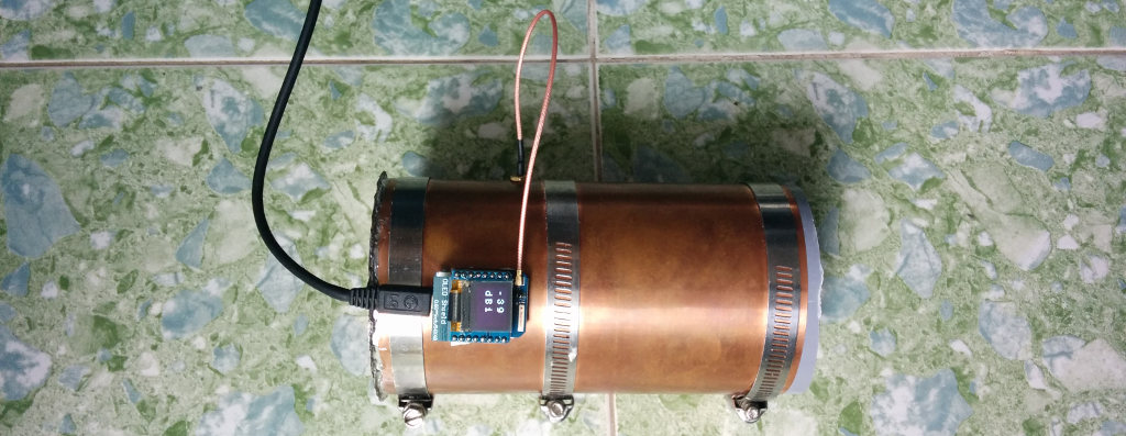
However, for about the same price as a large canned food item, I was able to purchase a sheet of 0.6mm thick copper. After measuring it out and cutting it, I wrapped it around the inside of an 80 mm PVC pipe, resulting in a tube about 79 mm wide. Later I found out it was easier to wrap the copper around the outside of the tube, and attach 90 mm diameter hose clamps to hold it in place. In both cases I soldered the result on to a copper base.
Then I measured and installed an IPEX antenna connector where the pickup wire should be before plugging a wire of the correct length into it. It seemed to work quite well, but it would be better if I could characterize it a little, or at least come up with a way to conveniently align a few cantennas. It turns out that it’s easy to get the RSSI (Received Signal Strength Indication) of the access point an ESP8266 running NodeMCU is connected to:
x = wifi.sta.getrssi()

print (x)
Using RSSI for Antenna Alignment
While RSSI is a vague way of measuring signal strength, it seemed good enough to align cantennas. To test it out, I set one cantenna-connected mini D1 Pro to both act as an access point and connect to my router.
wifi.setphymode(wifi.PHYMODE_B)
tries=0
ssid="Home Network Name"
pswd="myrealpassword"
--start by setting both station and AP modes
wifi.setmode(wifi.STATIONAP)
wifi.ap.setip({ip = "192.168.4.1", netmask = "255.255.255.0", gateway = "192.168.0.1"});
wifi.ap.config({ssid="Tenna",pwd = "foxhunting"})
tmr.alarm(0, 100, 1, function(Q)
if wifi.ap.getip() == nil then
tries=tries+1 --wait for AP to come up
else
tmr.stop(0)
print("after "..tries.." AP IP=",wifi.ap.getip())

--now connect to LAN
wifi.sta.config(ssid,pswd)
wifi.sta.connect()
tries=0
tmr.alarm(0, 100, 1, function(Q)
if wifi.sta.getip() == nil then
tries=tries+1 --wait for LAN to come up
else
tmr.stop(0)
print("after "..tries.." STA IP=",wifi.sta.getip())
dofile("server.lua")
end
end)
end
end)
Once the access point was running and it was connected to my router, any UDP packets it received on a certain port were set to be uploaded to an IoT data logger. I used Thingsboard, but other services would work just fine. I saw a range of -2 to -91 dBi this way, using Wi-Fi 802.11b.
port=10001
ClientID = 'put anything here'
token = 'put token here'

m = mqtt.Client(ClientID, 120, token)
srv=net.createServer(net.UDP)
srv:on("receive", function(srv, pl)
m:connect("mydomain.com", 1883, 0, function(client) print("connected") m:publish("v1/devices/me/telemetry", '{"RSSI":'..pl..'}', 2, 1) m:close() end)

end)
srv:listen(port)
A second cantenna-connected mini D1 Pro was programmed to measure the RSSI and send it to the first one as a UDP packet. I powered it with a small spare cellphone battery. This worked quite well and saved me a screen as I could just walk around with this system and leave my smartphone open on the IoT data logging backend. The range was quite good, passing through a number of concrete buildings. The UDP packet sending function crashed every few minutes due to what was reported as an ‘unknown error’, but rather than debug it, I called the offending function in protected mode (pcall) and since then it has worked flawlessly:
sda = 2 -- SDA Pin
scl = 1 -- SCL Pin
port=10001
sla = 0x3C
i2c.setup(0, sda, scl, i2c.SLOW)
disp = u8g.ssd1306_64x48_i2c(sla)
disp:setFontRefHeightExtendedText()
disp:setDefaultForegroundColor()
disp:setFontPosTop()
disp:firstPage()
repeat
pl = "Fox"
deg = "Hunt"
disp:setFont(u8g.font_profont17r)
disp:drawStr(0, 20, pl)
disp:setFont(u8g.font_profont17r)
disp:drawStr(0, 35, deg)
until disp:nextPage() == false

enduser_setup.start(
function()
print("Connected to wifi as:" .. wifi.sta.getip())
end,
function(err, str)
print("enduser_setup: Err #" .. err .. ": " .. str)
end,
print -- Lua print function can serve as the debug callback
);

function poll(level)
pl = wifi.sta.getrssi()
if pl == nil then
print "NC"
pl = "NC"
sla = 0x3C
i2c.setup(0, sda, scl, i2c.SLOW)
disp = u8g.ssd1306_64x48_i2c(sla)
disp:setFontRefHeightExtendedText()
disp:setDefaultForegroundColor()
disp:setFontPosTop()
disp:firstPage()
repeat
cee = "dBi"
disp:setFont(u8g.font_profont17r)
disp:drawStr(5, 15, pl)
disp:setFont(u8g.font_profont17r)
disp:drawStr(5, 35, cee)
until disp:nextPage() == false


else
sla = 0x3C
i2c.setup(0, sda, scl, i2c.SLOW)
disp = u8g.ssd1306_64x48_i2c(sla)
disp:setFontRefHeightExtendedText()
disp:setDefaultForegroundColor()
disp:setFontPosTop()
disp:firstPage()
repeat
cee = "dBi"
disp:setFont(u8g.font_profont17r)
disp:drawStr(5, 15, pl)
disp:setFont(u8g.font_profont17r)
disp:drawStr(5, 35, cee)


until disp:nextPage() == false
end
pcall(send)
end
function send(level)
pl = wifi.sta.getrssi()
if pl == nil then
print "NC"
pl = "NC"

else
print (pl)
udpSocket = net.createUDPSocket()
udpSocket:send(port,"192.168.4.1",pl)
end
end
tmr.alarm(1, 1000, tmr.ALARM_AUTO, function() poll(0) end)
One thing I noticed was that it was very easy to directly align the antennas using the RSSI reading, even without good line of sight. I started thinking it might be a good tool for locating rogue access points… so I added a small screen to display the RSSI of a chosen network, and used the ‘end user config’ function (included above) so my smartphone can instruct it to scan for and connect to arbitrary networks.
Field Testing as an AP Locator
I brought it to a coffee shop I knew I could try it at without irritating the staff. I was able to find the router in under a minute, which I probably could have done visually in about the same amount of time because it was just an off-the-shelf router left on a table in plain view – but the point was that it worked well. Then a few memories clicked into place and something occurred to me…
I had seen a restaurant months ago that had one more Wi-Fi network than made sense. There was a network for each floor, one that was clearly for the POS system, and then one more that had slightly different capitalization in the SSID. I didn’t think anything about it at the time, but it was time to go for a visit.
It was immediately clear that it was a rogue access point, because it used the same password as the staff gave me, but was redirecting me to download a file called ‘facebook.scr’ (what a blast from the past – why are .SCR files still executable?). The Internet still worked because the rogue access point was acting as a bridge to the proper Wi-Fi network.
So I downloaded the file, opened a terminal, and ran ‘strings facebook.scr > output.txt’, looked through it, and saw that it was run of the mill Bitcoin mining malware. There was enough information within the file to see the mining volume in the mining pool too. In any case, I had an access point to find!
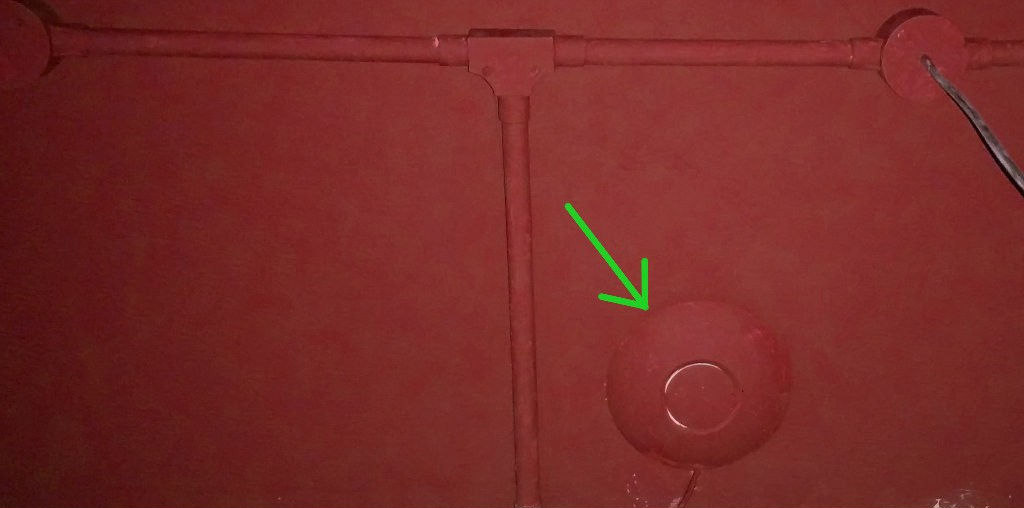
It was on another floor, but didn’t take long to find. The legitimate access points were just normal residential routers taped to the wall and were easy to spot, but the rogue access point was another story. It was clearly professionally installed at or before the time the business moved in: the wiring went through the same conduits as the electrical sockets installed in the walls. It was also painted over in exactly the same color of ceiling paint as everything else. In other words, it wasn’t just left around. It was very carefully installed, and probably consists of a commercial ceiling-mount Wi-Fi router with improved firmware.
More interesting still, was that the Bitcoin mining power of the pool was not huge, but much greater than a single such device would explain if it represents their primary vector. Given the careful installation, it’s possible that it is. I’m no masked vigilante though — I’ve passed my findings off to the relevant authorities, and they can deal with it as they see fit from here on.


Waiting for the next article: Making Rogue Access Points with the ESP8266. ;)
Yes please!!!!
Exactly, ha ha.
You mean this? https://hackaday.com/2015/05/03/esp8266-wifi-throwies/
Not completely familiar with the maths of directional antennas, but it would be nice to include the wavelength of 2.4 ghz so we could get a mediocre understanding of the diameter of your can.
wavelength = speed of light divided by frequency. In this case, very very close to 1/8 meter.
it’s a type of waveguide antenna, you can find the math for those pretty easily…
Except for being too small, the diameter is not that critical, however the placement of the feed is.
120mm/5″ I guess?
Jebus, ‘mashup’, really? Portmanteau.
Otherwise, good article, thanks!
Haha, I’ll take the blame on that and try to use those big fancy words next time ;-)
This was a fun jaunt down memory lane – war driving anyone?
Yep with my Pringles cantenna
The accesspoint is an ubiquiti one. I seem to remember that had issues in the past where their firmware could be remotely compromised (in the AirOS line). Maybe this is what happened?
This is a quite expensive relatively high performance AP to use just for rouge duty. Any 10$ cheapo thing would do for that.
Unlikely. There are cheaper clones that are visually identical (souce: My house). Incidentally it looks like it’s using PoE, be interesting to find the switch.
“… for rouge duty.”
It is painted red; was that a Freudian slip? ;)
I agree with your first point. At the very least, the perpetrator likely didn’t purchase the AP just for this task. It could also have been someone with unsupervised access and the ability to reset to factory defaults and reconfigure it undisturbed.
It seems to me that you are losing a lot of the antennas gain by having the antenna in the focal point of the can and than using that length of coax and the connector to get the signal out. I would put the ESP8266 with it’s built in antenna in the focal point. My guess is you would see an improvement in signal strength.
It should not be a problem. Even a crappy short pigtail like this together with connectors should have no more than 1dB loss. The project is also primarily using the directivity, and does not really need to sense the absolutely weakest signals.
Yes, once it’s so short, it makes little difference…probably have more loss on the connectors themselves rather then the coax.
Thing is – why even bother with the cable, why not just mount the ESP right onto the antenna feed?
It’s worth a try! I’ve got a lot of Mini D1 boards without antenna connectors (as opposed to the mini D1 pro). This would be a good way to put them to better use, especially if I put a cap on the antenna to weatherproof it.
The main issue though is that I’m working on something else with this too, and the esp8266 needs to be inside a thick metal box taking measurements. The cable lets me put the antenna outside the big metal box.
This may be another HAD project, but it would be cool to decide on one commonly available can that is wither big enough or a couple can be taped together to be big enough to make can part of the cantenna, and than 3D print a circular insert that would fit inside the bottom can and hold the ESP8266 in the proper place, so the antenna is both centered properly in the can, and the proper distance from the back.
As an aside, I was also pondering making one suitable for outdoor use and building up a box with a little hole at the bottom for the ESP8266 to it in. Part way through the print, you pause the print, stick the ESP8266 in place, pull the wires through the hole, and than let the 3D printer print the “top” on the box. When the print is done a small gob or RTV or epoxy could seal up the hole the wires come out of, leaving the ESP8266 safely sealed up. Between the 3D printed box and being shielded by the can, that should be a pretty weatherproof build. Even more so if the can has a plastic top you can put on when you are done, like a pringles can.
I agree there is not a lot of loss, but the connectors and the coax are the bad points and can be eliminated, so why not eliminate them. And don’t forget that 3db is double or half the power. One db is significant.
make it hard to see the screen though :P
Wouldn’t you need to shield the rest of the ESP8266 “amplified” wifi signal from causing problems.
What I meant to say was:-
Wouldn’t you need to shield the rest of the ESP8266 to stop the “amplified” wifi signal from causing problems.
(the comments system really, really needs an edit button).
I agree, it’s been far too many years without a time-out comment edit button on HaD. But then again, if you’ve been around here long enough remember how long it took HaD to allow comments containing any CAPS!
And direct replies
HAD did try a more modern fully featured commenting system, they didn’t like it and apparently gave up on finding an alternative, perhaps they should turn in their hacker credentials?
nice
“Cantennas” have been around since at least the 70s. Used for MDS television reception. Worked better before manufactures began trimming down can sizes to sell you less for the same price. A “one pound” coffee can actually held a full pound, not like 12 oz size now sold.
Like :)
Would love to know the make up of this rouge access point. But guessing it’ll be in a police evidence room for a long time.
I would assume that they chose the ubiquiti knock off because it looks like a commercial “rate of rise” heat detector (Think commercial smoke alarm). They are usually installed by the security company and all hardwired to the security panel. That would be the first place I would look for the POE switch. If its an all in one system, some security cameras are set up POE so its a great spot to hide this setup. I’ve just talked myself into being paranoid, guess im going to go look over my system when I get home from work