Hunting Rogue Access Points With The ESP8266

Cantennas outperform every consumer-grade Wi-Fi antenna I’ve had the bad luck of purchasing. Cantenna is a mashup of ‘can’ and ‘antenna’ creating the nickname for a directional waveguide antenna built from re-purposed steel cans. For anyone who has yet to build one, it makes an excellent afternoon project. Here are some build instructions and technical details. I went beyond that, and ended up catching a rogue WiFi access point in the process.

When I needed to extend the range of some ESP8266-based sensors, cantennas were right at the top of my list of things to try. It was easy enough to build one, attach it to a Wemos Mini D1 Pro, and call the job done… leaving me with plenty of time to over-engineer it, and I ended up down a bit of a rabbit hole.

The first thing I did was stop using cans. Canned goods are not only expensive in my corner of the world, but more importantly don’t lend themselves that well to making a standardized antenna in volume. I can also only eat so many beans! The latter reason alone is enough to consider an alternative design like a modular dish reflector.

Continue reading “Hunting Rogue Access Points With The ESP8266”

Visually Tune Your HF Antenna Using An Oscilloscope And Signal Generator

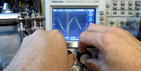
Lots of readers are into toying around with RF and ham radios. One thing that is always of concern is tuning the antenna. New equipment is never cheap, so whenever another option comes along that uses existing test gear it gets our attention. [Alan Wolke] aka [w2aew] covers a process he uses to tune his HF antenna using a signal generator and oscilloscope.

The process is more of a teaching aid than a practical replacement for commercial equipment mostly because proper signal generators and oscilloscopes are large items and sometimes not available or affordable. That said, if you do have such test gear you only need build a simple breakout board containing a form of wheatstone bridge where the unknown Rx is the antenna. Two oscilloscope probes are connected across the bridge balance nodes. Some special care needs to be taken matching probe cable length and 50 ohm input impedance to the oscilloscope. A couple of 1K probe coupling resistors are also needed to prevent affecting the impendence at the hookup points. Once the selected signal is injected you can adjust an antenna tuner until the two voltage waveforms match on the oscilloscope indicating your antenna network is tuned to 50 ohm impedance with no reactance.

Being able to tune your antenna visually can really help you understand what is going on in the turning process; matching not only input impedance but also phase shift indicating inductive or capacitive reactance. Join us after the break to see the video and for information on what’s presented in the second part of [Alan’s] presentation.

Continue reading “Visually Tune Your HF Antenna Using An Oscilloscope And Signal Generator”