
Current. Too little of it, and you can’t get where you’re going, too much and your hardware’s on fire. In many projects, it’s desirable to know just how much current is being drawn, and even more desirable to limit it to avoid catastrophic destruction. The humble current shunt is an excellent way to do just that.
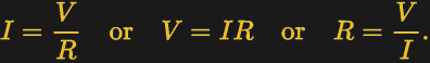
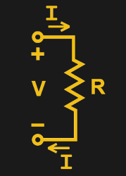
To understand current, it’s important to understand Ohm’s Law, which defines the relationship between current, voltage, and resistance. If we know two out of the three, we can calculate the unknown. This is the underlying principle behind the current shunt. A current flows through a resistor, and the voltage drop across the resistor is measured. If the resistance also is known, the current can be calculated with the equation I=V/R.
This simple fact can be used to great effect. As an example, consider a microcontroller used to control a DC motor with a transistor controlled by a PWM output. A known resistance is placed inline with the motor and, the voltage drop across it measured with the onboard analog-to-digital converter. With a few lines of code, it’s simple for the microcontroller to calculate the current flowing to the motor. Armed with this knowledge, code can be crafted to limit the motor current draw for such purposes as avoiding overheating the motor, or to protect the drive transistors from failure.
In fact, such strategies can be used in a wide variety of applications. In microcontroller projects you can measure as many currents as you have spare ADC channels and time. Whether you’re driving high power LEDs or trying to build protection into a power supply, current shunts are key to doing this.
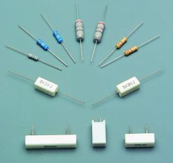
With the theoretical side of things covered, it’s here that we veer towards the practical. If you’re new to electronics, when you hear “resistor”, you’re probably thinking of a little 1/4 watt beige device with some colourful bands indicating the value. However resistors come in all shapes and sizes. In fact, everything except superconducting materials have resistance – even just bare wire! So when you’re choosing a resistor to use as a current shunt, where should you start? The first thing to remember is that power loss is relative to resistance.
The power lost in the resistor is equal to the current squared, multiplied by the resistance. 
What this means in practical terms is that in some cases, a link of wire is chosen to act as the shunt. This is prevalent in many applications, such as motor controllers you might find on an electric skateboard or e-bike. As long as the resistance of the wire link is known, it can be used to calculate the current passing through it.
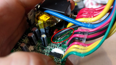
The shunt is generally used to protect the speed controller from a load drawing too much current, or to limit the speed of the attached motor. If you want to play fast and loose with such a controller and are thirsty for more speed, there’s a simple trick. By cutting the connection from the shunt to the controller’s sense line, and instead tying the sense line to ground, it will appear as if no current is flowing since no voltage drop is measured. The speed controller will respond by giving all the power it can, which usually ends in flames as the transistors in the controller fail under excessive load.
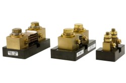
Other times, a very accurate current shunt may be desired during the bench testing of equipment. In this case, a precision current shunt may be used with a voltmeter to determine the current passing through the circuit. Typical shunts are generally rated to have a voltage drop of 50 mV at their rated current. Armed with a suitably sensitive voltmeter, it’s possible to measure large currents relatively safely – something not achievable with the average multimeter.
These are just a handful of ways current shunts can be used. Fundamentally, proper current measurement can make a wide variety of projects safer, more robust, and more reliable. The key is applying the basic principle of the current shunt with the correct hardware for your application, which will ensure that any measurements taken are reliable and safe.


Obligatory:
https://www.youtube.com/watch?v=j4u8fl31sgQ
“the dumber you are the more likely you are to invent a light bulb”
lmao
Haven’t watched Electroboom in ages. Man, he’s still got it.
I dont like the click-baity-ness of his videos but , have to say behind the stupid sparks and shocks there is good content.
There’s got to be a rhyming joke in here somewhere but I can’t quite put my finger on it
Hmm, let’s see.. OK, folks… here we go!
Shunt, shunt mo munt.. banana fanna bo bunt… fe fi fo funt……. shunt! ( Nope)
Shunt, shunt go gunt…. wanna nanna wo wunt… te ti to tunt….. Shunt! (Nope)
Shunt, shunt co cu..! (THERE IT IS!)
I must say… the emphasis on the word SHUNT… gets a bit old after about 5 seconds.
“…it’s possible to measure large currents relatively safely”.
Current shunts are not intended to ‘be safe’ (although an NRTL assessment engineer will allow you to put a shunt on the safety-critical component list of a product after tests and verification of ratings). There is no galvanic isolation between whatever circuit the shunt is inserted into and the meter and yourself. The human should implement a test configuration that provides isolation where the voltage or power or current levels are considered hazards. Do not connect non-isolated test equipment to a shunt used to measure AC mains.
Should have also mentioned what makes an resistive material suitable for use as a shunt – the tolerance offered per the temperature coefficient. The example provided used bus wire as a shunt, which can be accurate, but only over a narrow temperature range. Have used PCB traces as shunts, but only for small currents , and with a transistor straddling the trace to measure temperature (design resulted in about 1% accuracy over 0 to 50C).
For ‘extreme’ accuracy requirements, typically use manganin shunt, and carefully controlled signal and load current paths. Also like to mechanically isolate the shunt and attach an RTD to the sensor and normalize the reading, with a temperature-controlled fan indirectly blowing into to shunt compartment. Mostly we have a test stack at the factory that needs to do testing at 100ppm.
Yes 4 wire measurement (“carefully controlled signal and load current paths”) are very important. But regarding isolation and safety: In a lab setup not everything has to be consumer-proof. Air insulates and you know where not to put your fingers. :-)
Hey accidents still happen.
Have you never slipped and accidentally put your finger in a live circuit before? No? Anyone?
Alright nevermind. :-)
Those who did aren’t alive to post comments here ????
No, I think there could be a couple of reasons, some might be too embarrassed to post, or in my case, I just saw the thread.
Over the last 35 years I have worked as a ET(US Navy), EE(after school) and Electrician(Under a master) at various times and I’ll admit that I’ve gotten tingled by 120/240 more than once, and in all cases, it was because I(and in one case someone else) got in a hurry. The one time it was someone else I was wiring in a 240 socket for a Dryer and someone flipped the breaker, even with a bright yellow tag on it, they had came home after I started working on it; I did not even know it until the outside of my arm brushed a bare wire(I use leather gloves which are quite good insulators).
Most of my DC work is at 13.8VDC or below, but one time as a Navy ET, I was working on a power amp and got zapped my one of the output caps. Yes, the equipment was turned off and I had drained all the caps, but was then I was distracted for a couple of hours by something else. I went to go make a measurement and somehow the tip of my left forefinger ended up on a positive bus bar and SHAZAM! To this day I’ve got a no feeling in the middle of that finger and there is a dent where it was burned. It was also a rough introduction to cap bounce-back, dialectic absorption or whatever you want to call; Back in the eighties at least it was not covered in BE/E.
0 ohm resistors can actually be used as very low cost and convenient-to-place shunts. Most I’ve used have a drop of about 20mOhm. With two in parallel, you can get away with measuring 7.5A in a 0805 package.
Hmmm Ethan,
Most interesting paradigm, my neural virtual HP-41C (still in training) tells me . . .
that surely 7.5A (max?) likely be rather low duty cycle overall – such as what ?
As your typical I^2R runs to 0.562 Watts spread between those 0805 packages,
so pray tell what the thermal resistance temp rise works out too re what NTC/PTC
upper end characteristic and in what enclosure and I guess not an intrinsically
safe as a “casual customer’s alpha test” we declined to advise them of ;-)
They have “up to 50mOhm” and are rated for 2 or 3 amps max. So they have like -50/+150% tolerance. Not really good for measurement applications. Why not use real 10 or 20mOhm shunts?
Am I really that old that I learned Ohm’s Law as E=IR? Since when did “E” switch to “V”? All of my old text books show Volts a “E”. Wait, maybe I do not want to hear this answer?
It confused ’em, or it’s to confuse we that be ancient.
Maybe not good idea to complain as they haven’t noticed I yet.
When I learned Ohms Law, yeah it was E, Makes for neater mnemonics – eg “pie” -> P = I x E.
But, for us old timers*, that was long before the Raspberry Pi came on the scene.
*Back when the math symbol “pi” was equal to 2!
It wasn’t before raspberry pie was on the scene.
The funny thing, if another researcher hadn’t been such a perfectionist, the unit of resistance would be now known as the Cavendish… now doesn’t that thought just drive you bananas?
My background is chemistry and chemometrics and I thought A = current. I guess I think that since A is the unit amps. Amazing how simple some of the electronics circuits/systems are and I really smile how dumb I feel reminding myself how easy, really the variables are as well as the associations. Either I never thought about before or completely missed the point. I think not being around pirate chemists is helping also.
Another fun one, In Electrical Engineering, the imaginary unit ‘i’ is usually written as ‘j’, because ‘i’ is already used for current.
Gotta be fussy here; No. I is for Amps.
j is ti show a lower case incursive i.
When incursive is no longer taught, who knows…
TT, 2 capital T’s, works for pi.
Well yeah though some dweebs see the capitals as shouting !
think it best all peoples get grounding in engineering of some
sort with psyche as they both help with ‘complex’ numbers :D
Show me your TT’s!
“Well yeah though some dweebs see the capitals as shouting !
think it best all peoples get grounding in engineering of some
sort with psyche as they both help with ‘complex’ numbers :D”
If someone sees capital letters in formulas as shouting, I can’t help them. Maybe they can find a safe space with kittens, coloring books, and a ball pit.
There is no such thing as being too pedantic when it comes to using proper case and punctuation in engineering and electronics. I just saw someone on Quora ask for the energy of a photon with “wavelength of 110N.m”. I doubt they meant newton-meters, but that is what the question said.
I was taught that too, but I think that is a myth that has grown over time.
I believe the real reason ‘j’ is used by electrical engineers is that ‘j’ is the second basis unit used in ‘ijk’ vector notation. Electrical Engineers were some of the first users of the modern notations used for differential equations and vector calculus due to their sudden heavy use for industry in the late 19th century for electrical engineering related functions. So I believe the theory that j is used, because then the basis element has the same name for expressing both complex numbers and vectors and avoids confusion especially when looking at random calculations out of context.
Yeah… except the vectors are written with hats on them: î, ĵ and … compose keys in X.org won’t do the k version.
They are simplifications of Maxwell’s equations so you can use these instead if you feel first order is beneath your dignity.
Maxwell is, to me, more important than Einstein in his achievements in science. So, I had to read as I forget physics. Then in reading I found “I” actually is the “net electric current” and “J” is the “electric current density.”
The net electric current I is the surface integral of the electric current density J passing through a fixed surface, Σ:
{\displaystyle I=\iint _{\Sigma }\mathbf {J} \cdot \mathrm {d} \mathbf {S} ,} {\displaystyle I=\iint _{\Sigma }\mathbf {J} \cdot \mathrm {d} \mathbf {S} ,}
https://en.wikipedia.org/wiki/Maxwell%27s_equations
Electromotive force is so 20th century.
It’s still around in the physics textbooks. When you start approaching electronics from the concept of charge units, I guess it’s good to infer the “forces” involved and not just take the presence of volts for granted.
It’s all about USB phone chargers these days.
how about Conventional Current v. Electron Flow?
Don’t you dare open that can of worms!! I was struggling to fully understand how circuits worked until I figured out electron flow. After that, everything damn-near made sense… except mesh analysis. I hate mesh analysis with a passion. I avoid it like a plague.
PNP transistors do not use electrons as a majority carrier. They use holes……
It is still electrons moving around. Holes are just a simplification.
When I learned Ohm’s law it was U (I’m from Sweden though so that might explain it :)
I learned it as U=IR, could have been a Dutch thing… (My stupid head made the mnemonic “Ultraviolet = InfraRed” to remember the order)
In Switzerland we learned it as U=R*I, because the canton of Uri is well known here. It is one of the three founding cantons that started Switzerland as we know it around the year 1291.
So will we get a nice series of articles now: (accuratly) measuring xurrent? Would happily Looking forward to.that!
The voltage drop across a 1K ohm resistor is equal to the milliamps flowing through it.
For mid-range current sensing I’m fond of these: https://www.adafruit.com/product/1164 . I’ve used dozens of them. There’s also an I2C version based on the INA219.
Who draws these articles? I would like to see the complete collection of these
Joe Kim
Is it possible to use a shunt resistor to measure AC power draw?
Maybe with the use of an o-scope but, unless you have the right protections, I’d advise against it. One stray spike can destroy your oscilloscope. Might need to put a cap on it to be sure.
Damn right mate,
Even with all the power factor corrections around on switch mode supplies
there are all sorts of odd ball harmonics around such as the so called triplen
on 3 phase 50Hz feeds which can result in 150Hz on a single phase line coupled
from the neutral/ground line and with serious mechanically switched
discontinuities causing reflections all over the place.
Good thing about current transformers is the intrinsic damping as well as great
isolation caps across shunts in AC systems can help but I’d suggest also adding a
carefully selected metal oxide varistor which nowadays I hear you can print more
or less directly on the inside of insulating enclosures or on pcbs in high volume
products…
Love is like oxygen
You get too much, you get too high
Not enough and you’re gonna die
Love gets you high
– Sweet
Thanks for the article on how CURRENT shunts work. Now can you enlighten us on how FORMER shunts worked?
B^)
I think they like it better when you pronounce the “sh” as more of a hard c or k sound.
At least I have the couch though I guess.
Knew of an engineering student who was in the lab. He and his lab partner did everything correctly up to removing the current shunt across a meter. They cranked up the juice and were supposed to have a reading of 1 A on the meter. They never got it to the 1 A point because the wiring was smoking. They shut everything down and disconnected everything. The shunt? They discovered that in the process of tearing down the equipment. He said they had hundreds of Amperes flowing through the setup.
If only these shunts were perfect resistors. As soon as you don’t just measure static DC currents anymore, a whole new world of parasitic inductance opens up to you…
Aww come-on, don’t make me be THAT guy. Where was Al W. on this one?
“Shunt” is a misnomer. A shunt requires a parallel connection that diverts current. For example, a crowbar circuit.
https://en.wikipedia.org/wiki/Shunt_(electrical)
A current sense resistor is just that, not a shunt.
If you were to measure a resistor’s voltage to infer current, the voltmeter would be more akin to a “shunt” than the resistor.
“Shunt resistors” are used to load a current-source like some transformers and are always connected parallel to the secondary/load.
There are various reasons you would want to do this, but one is power regulation. Sound wasteful? That’s because you’re thinking of a quasi constant voltage supply.
If you want to regulate a voltage supply, you can adjust a SERIES resistance. If you want to regulate a constant current supply, you adjust a SHUNT resistor in parallel with the load.
Counter-intuitively and opposite of a typical voltage source, output power decreases as load resistance decreases with a constant current supply.
So with a low resistance SHUNT installed, the output is low. Remove the SHUNT and the output increases.
Math it.
Now that would make a better article.