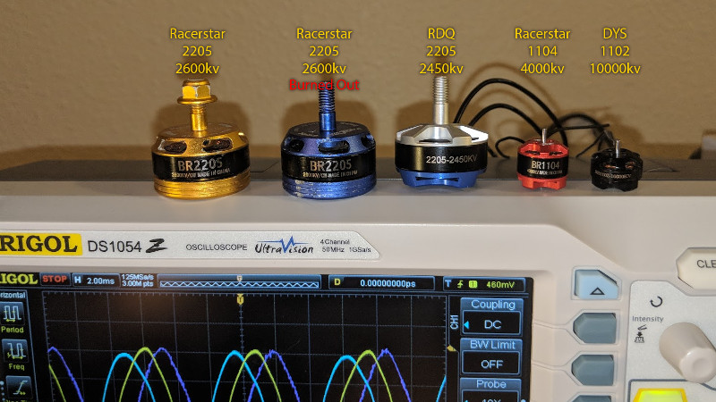
We always like finding new excuses reasons to use our test equipment, so we couldn’t help but be intrigued by this tip from [Joe Mosfet]. He uses the ever-popular Rigol DS1054Z to demonstrate the differences between a handful of brushless motors when rotated by his handheld drill at a constant RPM. Not only is he able to identify a blown motor, but it allows him to visualize their specifications which can otherwise seem a bit mystifying.
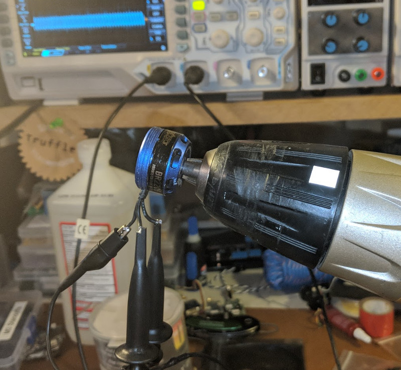 One wire from each motor is used as the ground, and channels one and two are connected to the remaining wires. Despite the DS1054Z having four channels, [Joe] is actually only using two of them here. The third channel being displayed is a virtual channel created by a math function on the scope.
After wiring them up, each motor got put into the chuck of his drill and spun up to 1430 RPM. The resulting waveforms were captured, and [Joe] walks us through each one explaining what we’re seeing on the scope.
The bad motor is easy to identify: the phases are out of alignment and in general the output looks erratic. Between the good motors, the higher the Kv rating of the motor, the lower voltage is seen on the scope. That’s because Kv in the context of brushless motors is a measurement of how fast the motor will spin for each volt. The inverse is also true, and [Joe] explains that if he could spin his 2450Kv motor at exactly 2450 RPM, we should see one volt output.
Beyond demonstrating the practical side of Kv ratings, [Joe] also theorizes that the shape of the wave might offer a glimpse into the quality of the motor’s construction. He notes his higher end motors generate a nice clean sine wave, while his cheaper ones show distortion at the peaks. An interesting note, though he does stress he can’t confirm there’s a real-world performance impact.
Last year we featured a similar method for identifying bad brushless motors using a drill press and an oscilloscope, but we liked that [Joe] went through the trouble of testing multiple motors and explaining the differences in their output.
[via /r/multicopter]


That link to imgur is invalid :(
Seems to be syntactically correct and working here… what’s invalid about it?
I’ve had a couple people check now and it has come up for them. What is it coming up as?
The first few times I tried it had the imgur banner and just said something along the lines of the page you are accessing is invalid. A short while later it all worked . ( and people expect us to trust self driving cars LOL)
Hmmm all good now :)
Why are the phases not 120 degrees from each other? It looks more like they’re 60 degrees off instead.
I think the middle phase might be a function generated by the oscilloscope. This would place the actual phases at 120° apart as you’d expect.
Due to the way I wired the ground up to one of the motor leads, I had to measure one of the phases “backwards” from each other. If you were to invert the “yellow” phase, you’d see that they are equally spaced at 120 degrees.
Can someone shed a light on trapezoidal vs. sinusoidal back EMF? Many sources (e.g. https://www.motioncontroltips.com/faq-trapezoidal-back-emf/ ) state that most BLDC motors have trapezoidal back EMF. It seems to me that when connecting the motor to scope and rotating it, that should cause a trapezoid to show up.
To me the waves in that imgur look quite sinusoidal, but are they really more like trapezoids? The sides are maybe a bit too linear and the tops a bit too angular?
You nailed it, what they’re seeing is almost certainly because some of the motors are designed for BLDC and the others are AC motors. The back-emf waveform is also what the ideal input waveform would be, because the moving magnetic field caused by mechanical rotation is just opposite of the moving electric field that would drive the motor. A slewed-square output from a MOSFET is closer to trapezoidal than to sinuoidal so it is more efficient in BLDC applications, whereas sinuoids would be more efficient / better in larger designs for different reasons (no CEMF, sum is zero, etc).
https://www.motioncontroltips.com/faq-trapezoidal-back-emf/
Why do they call this type of motor brushless DC motors when the are just three phase AC motors?
Not sure, possibly because they use DC instead of AC.
Because these motors are powered from DC by regulator…
As are all AC motors when they are run through a variable frequency drive. That’s VFD to the power people and ESC to the toy/hobby people. Personally I can see absolutely no difference between the two types of motor..
Heck. I’m still wondering why they’re rated in Kilovolts?
It’s not killivots it’s kv , velocity constant. A constant velocity per volt.
And of course the first link in search results, has a rotor with obvious commutator for the “brushless motor kv” article.
http://learningrc[dot]com/motor-kv/
I despise the use of stock photos.
Really casts doubt on the general accuracy of anything you see them in.
Anyone got a link to an article that looks like the author cared a little?
I hate having to read a dozen or more articles, to try and figure out the errors.
Hmm. seems you can’t bracket part of the URL to make it a non active link.
http://learningrc.com/motor-kv/
so much for my accuracy huh! xD
The photos don’t look like a real 3-phase signal (with a 120° phase shift between the phases). Maybe it would be better to create a virtual ground by wiring three (equal) resistors from the motor connectors to the ground connection of the oscilloscope. Then all three phases can be measured by connecting all thee connections of the motor to independent channels of the oscilloscope.
The yellow phase is simply negated; we’re seeing all three phases.
Assuming it was done on purpose, negating one actually seems pretty clever to me, as it makes it easier to compare the phases’ waveforms (simply since they’re closer).