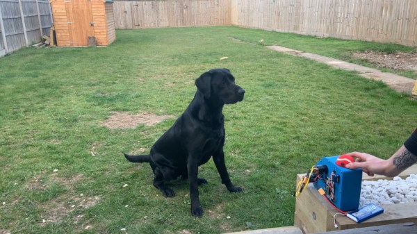
If there’s one bright spot on the blight that is this pandemic, it’s got to be all the extra time we’re spending with our pets. Dogs especially love that we’re home all the time and want to spend it playing, but sometimes you need to get stuff done. Why not head outside with your laptop and keep the dog happy with an automatic ball launcher?
 This is a work in progress, and [Connor] plans to publish a BOM and the STL files once it’s all finished. For now, it’s a working prototype that shoots a ball into the air and about 25 feet away, from the looks of it. Far enough to be fun, but not so far that it goes over the fence.
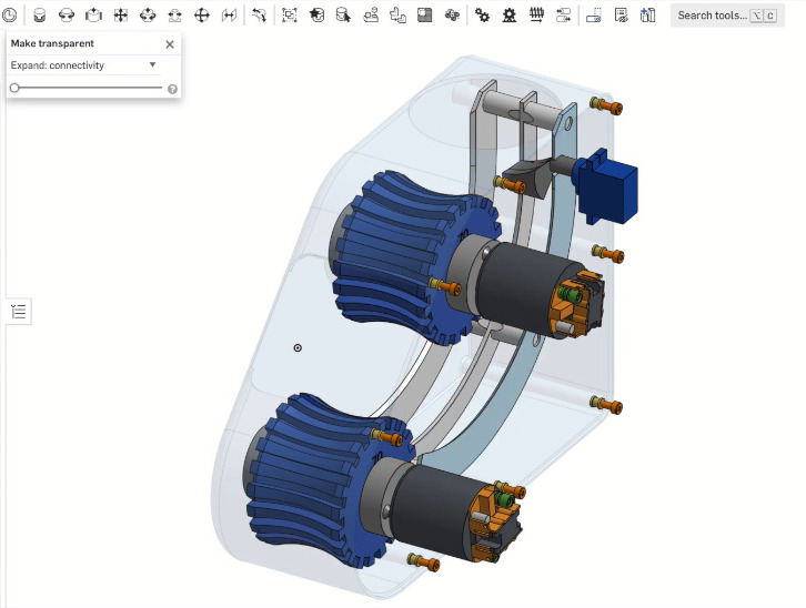
All [Connor] has to do is drop the ball in the top, which you know is going to lead to training the dog to do it himself. A proximity sensor detects the ball and starts up a pair of 540 R/C motors, then a servo drops the ball down the internal chute. The motors spit the ball out with great force with a pair of profiled, 3D-printed wheels that are controlled by a Turnigy ESC and an Arduino Nano.
In the future, [Connor] plans to print a cover for the electronics and enlarge the funnel so it’s easier for the dog to drop in the ball. Check out the brief demo and build video after the break.
All dogs should be able to get in a good game of fetch as often as they want, even if they happen to be blind.
Continue reading “Auto Ball Launcher Will Be Your Dog’s New Best Friend”
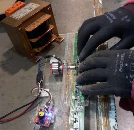 They say necessity is the mother of invention. Sometimes the necessity is simply avoidance of unpleasant tasks such as cutting down 3500 header pins by hand. [Nixieguy] and his coworkers were faced with 50 prototype boards bearing 70 overly long pins apiece. He saved them from cutting them all down by hand by making


