If you’re interested in 3D printing or CNC milling — or really any kind of fabrication — then duplicating or interfacing with an existing part is probably on your to-do list. The ability to print replacement parts when something breaks is often one of the top selling points of 3D printing. Want some proof? Just take a look at what people made for our Repairs You Can Print contest.
Of course, to do that you need to be able to make an accurate 3D model of the replacement part. That’s fairly straightforward if the part has simple geometry made up of a primitive solid or two. But, what about the more complicated parts you’re likely to come across?
In this article, I’m going to teach you how to reverse engineer and model those parts. Years ago, I worked for a medical device company where the business model was to duplicate out-of-patent medical products. That meant that my entire job was reverse engineering complex precision-made devices as accurately as possible. The goal was to reproduce products that were indistinguishable from the original, and because they were used for things like trauma reconstruction, it was critical that I got it right.
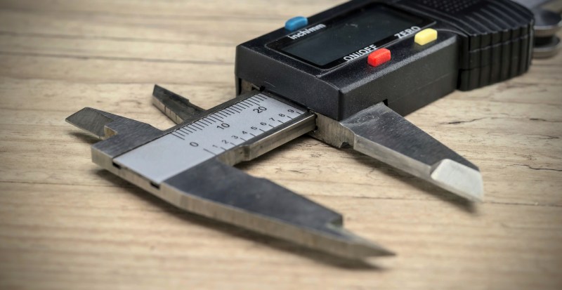
We were reverse engineering parts with features that were too small to be seen by the human eye, so we had some fancy equipment like high-magnification optical comparators. But, for the parts most hobbyists want to make, all you’ll need is a set of digital calipers. Very precise models can cost hundreds of dollars, but basic digital calipers can be found for well under $30—and that’s probably all you need.
Two Important Skills
Why are calipers the only measurement tool you need? Well, the human brain is very bad at estimating lengths with any kind of accuracy. “About 5 inches?” is the best most of us are capable of. So, you need a way to get accurate measurements for reference features. Conversely, however, the human brain is very good at two things: making relative judgments, and making inferences.
Relative Judgments:
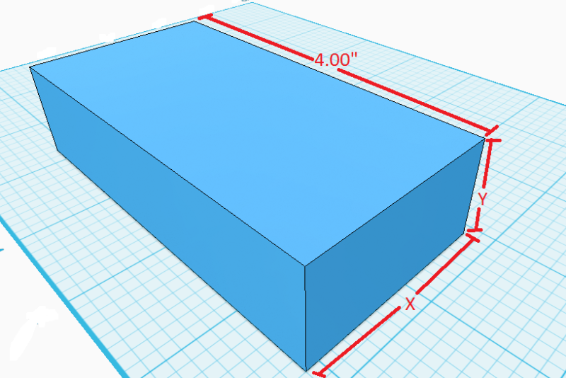
This is why you can look at an analog clock without numbers, and still guess the time with pretty good accuracy. It’s why you can look at a glass and say “yup, that’s about half full.” In regards to reverse engineering, it’s why you can look at the picture above and deduce that X is probably 2″ and Y is probably 1″.
Inference:
This is the most important skill you need to develop for successful reverse engineering. It’s all about making logical deductions from your measurements, based on the fact that the original part was designed by another human. For instance, if you measured a part like the image above, it might come out to 3.99″ instead of 4.00″. You can probably infer that the person who designed intended it to be 4.00″, and that the 0.01″ difference was probably a result of manufacturing tolerances, or a slight error in measurement.
As humans, we like to use nice even numbers when we design parts. Lengths, diameters, and radii are usually round numbers in the design phase. Angles are usually even divisions of 90 degrees—almost always something like 15°, 45°, or 60°. Of course, the caveats here are measurements that either the designer didn’t explicitly specify (like the hypotenuse length of a triangle), or when the designer has to use a specific measurement to interface with another part or has a similar design constraint (like with an injection molded part, where you need a draft angle of 1 or 2 degrees).
When making inferences, you’ll also need to take into account whether the designer was working with metric units or standard units. If you take a measurement with your calipers and it comes out to 0.197″, you might assume it’s due to manufacturing and guess it to be 0.200″. When, in reality your calipers were actually rounding up 0.19685″, which is exactly 5mm.
The Process:
I use a basic workflow of five steps when reverse engineering a part. As when you’re designing a part from scratch, you should start with a rough shape and add features to make it more detailed.
Step 1: Determine units
Start by asking yourself where the part was made, and more specifically where it was designed. A part originating outside of the United States is probably metric, but what if it was designed by an American company and simply manufactured overseas? Alternatively, what if it was designed overseas, but with the purpose of interfacing with an American product?
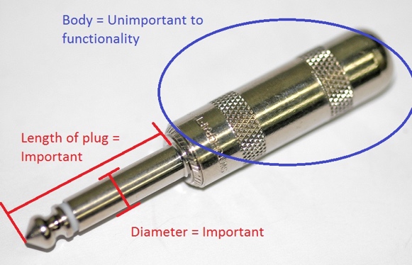
Let’s take a look at headphone plugs to illustrate the complexity of this problem. The original standard plug was an American design and the specifications call for a diameter of 1/4″ (6.35mm) on the barrel of the plug. The mini headphone jack, which became popular later and is probably what you have now, is exactly 3.5mm (0.137795″). I can’t find solid information on this, but I assume that’s because it was designed for international standards.
Once you have a hunch about the units being used, try taking some measurements in inches and millimeters on some major features, like the length, width, or diameter of the main body. See which (inches or millimeters) are closer to nice round numbers, while still keeping in mind that manufacturing is never perfect, and they probably won’t be dead on.
Step 2: Important primitives
Start by taking measurements of the main features of the part, and modeling those. It’s best to start with features that would be primitive solids, in order to get an accurate base. You also want your most accurate measurements (which are usually the first ones) to be the “important” features. These are features which affect the functionality of the part, such as where it will mate with another part.
Using the headphone plug as an example again, you can see that the plug barrel is very important to the functionality of the part. It’s what interfaces with the audio output device’s jack, and so it’s critical to get those measurements as accurate as possible. The body of the plug is used for two things: to house the wire connections, and to provide a gripping surface. Neither of those things is especially dependent on accurate dimensions. Therefore, you should start with designing the plug barrel — specifically by beginning with a cylinder based on the overall length of the barrel and its diameter.
Step 3: Unimportant Primitives
Next, it’s a good idea to go ahead and model the rest of the primitives that aren’t as important. The reason you want to do this before getting to the details of the important parts is simply a matter of logistics. It can sometimes be difficult to add major features without a nice “clean” primitive to reference. There are ways around that of course, but it’s usually best to have a complete “rough-in” of your part before you begin with the detail work.
Step 4: Important Details
Now that you’ve got your rough part, it’s time to start adding the important details. This is the most difficult part of the entire process, as those details are hard to measure but are still essential to the functionality of the part.
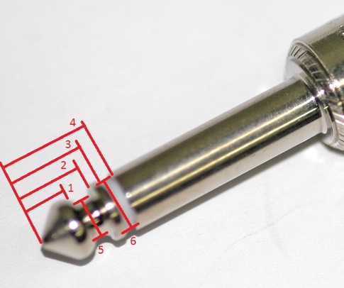
For this plug, you need to get measurements for each of the two revolved cuts into the primary cylinder that you started with. To do this, you need their diameters (5 and 6), as well as information on their positions (1 and 3) and their widths (the difference between 2 and 1, and the difference between 4 and 3). Why measure from the tip, instead of from the other end? Because the tip is what actually fits into the female jack, so the distance of these features from the tip is more relevant than the distance from the grippy end. You also need to be careful not to stack tolerances — all measurements should be taken from a hard point. That’s because each measurement you take will have a margin of error, and you don’t want those errors to add up.
The tip is next, which presents a problem: how do you measure the angle of the tip? You could use a protractor, but that’s not necessary and could present its own problems. One way would be to measure the distance from the tip to the widest point. But that will give you accuracy issues caused by the rounded tip and the beveled (fillet) edge. There just aren’t any “hard” edges to measure from. Instead, a better way is to make some inferences on the angle and the choices the original designer made. Drawing lines on a photo can be surprisingly helpful, especially if your software has 2D CAD-like measuring capabilities.
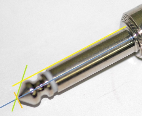
Right away, we can see that the angle between the center axis (blue line) and tip slope (green line) looks pretty darn close to 45 degrees. That’s about as round of a number as you can get, and it’s probably safe to assume that was the original design intent. But, did you notice that another problem has come up? The intersection of blue and green lines isn’t at the end of the tip (orange line). This is because instead of having a sharp tip, it was made with a blunt rounded tip. That means that when modeling the tip, you can’t easily use the green/blue intersection as a reference point for the revolved cut.
Instead, you can make the reference the intersection of the green and yellow lines. Now, this is also an imaginary point, as there is no hard edge there. The fillet makes it impossible to get a perfect measurement with calipers. But, it should be a little easier than the tip. Making a 45° revolved cut from there would leave you with a flat tip, which would then be rounded with an edge fillet (the fillet radius matching the radius of the circle of the flat tip).
For the rest of the fillets on the plug, you’re going to have to guess and make inferences. Try some different radii until they match those of the part. Getting this right takes some practice and experience, but it shouldn’t be too hard to get it close. Luckily, the radii of bevels (fillets) and dimensions of cut off edges (chamfers) aren’t integral to the functionality of the plug, because they’re just there for the spring clip to grip. So, it just needs to be close.
Step 5: Unimportant Details
This last step is pretty easy, because it’s not essential that you get it exactly right. On our headphone jack, the “grip” area could be completely different from the original part, and it would still work just fine as long as the wire connectors still fit inside. You can make it look like the original part, or you could take some artistic liberties (like knurling the entire area for better grip).
Now, I’ve obviously simplified the modeling of this particular part. In reality, it’s actually an assembly made up of a few parts to allow internal wire connections, and an electrical connection to the female jack. If you were actually trying to reproduce this jack (a TRS connector specifically), you would have to take it apart and model each part individually. But, hopefully this has given you an idea of the process you would need to use.
What If You Don’t Have Access to the Original Physical Part?
This is a challenge you might tackle if you were trying to reproduce the likeness of a product, or if you’re modeling for purely aesthetic reasons. Maybe you want to 3D print a prop from a movie, or you want to make a reproduction of a rare product you can’t get your hands on. The latter was the case for me when I modeled this Braun SK2 radio. All I had for reference was this photo I found on Google.
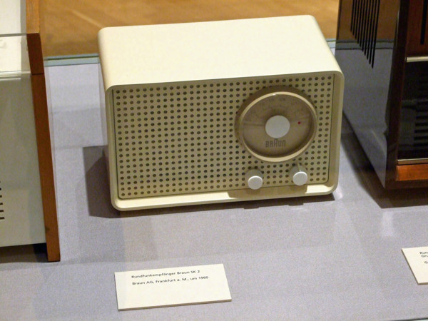
So, how do you model an object you don’t have physical access to? Well, most importantly, it wasn’t necessary for it to be exactly right. I wasn’t planning on actually making a physical radio, and even if I was it wouldn’t have needed to interface with any original SK2 parts. All that mattered was that it looked right.
Of course, the goal is always to make it as close as possible. In this case, I started with what I knew: this was a radio designed by Dieter Rams during in his heyday at Braun. At that time especially, Rams was obsessed with simple aesthetics, and so I knew he would have designed this radio with straightforward proportions and only non-frivolous features. Furthermore, Rams is German, so I could safely assume he was using the metric system.
I got a basic sense of scale by looking at the dial and controls in the photo. The dial needs to be readable (probably from arm’s reach), so that gives a minimum size for the radio. The knobs are obviously intended to be manipulated with your fingers, so it’s easy to make some inferences on their size based on that. They couldn’t be too large, so that gives a maximum for the size of the radio.
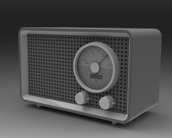 With a good idea of the general size of the radio in mind, I could come up with the proportions of the body. The height appears to be about 1/2 of the length, or at most 2/3. The depth appears to be between 1/3 and 1/2 of the length. The dial and controls take up 1/2 of the face/speaker grill. Of that half, the dial takes up about 3/4 and the knobs take up 1/4. The holes in the grill are in a square pattern, and so that’s a simple matter of counting how many rows and columns there are. The spaces are close to the same size as the holes, so that tells us the diameter of the holes.
And from there, it was mostly just about making the details look right. It takes a little bit of experimentation to get a good match, but you can always tweak the model as you go. It might not be perfect (you may notice that I got the proportion of the center plastic in the dial wrong), but the idea is make it visually accurate. At the beginning of this article, I mentioned that the human brain is terrible at guessing exact measurements, but good at relative judgments. That’s why it’s best to focus on getting the correct proportions between distinct features.
Working that way should allow you to make convincing reproductions without taking measurements. The more references you can find visually, the more accurate you can make the reproduction. If you were trying to reproduce a movie prop, for example, you could use the entire scene to make relative judgments. You might use the actor’s hands as a reference, or a pen on a table — or really any familiar object that you can use for scale. Take advantage of any other items in the frame to get a better idea of the size of the object you’re trying to model.
Featured Image: “Digital caliper close up” © Thomas Photiou | Dreamstime.com


“About five inches”: I guess a lot of people can’t even estimate that right.
measure your hand and you will find out how many inches you can estimate
To borrow a saying, it’s not how accurate it is, but what you do with it. :-D
That’s true. But I am quite good in estimating how many centimeters (or meters, millimeters) something is. I am just not good with this strange American units.
These article steps are also handy for those modeling things for game levels.
One challenge I have right now is modelling the body of a connector, using the receptacle it is designed to plug in to. It’s a unique connector, not a standard part or I would just order one.
I thought the sensible way to do this would be to use the receptacle as a mold; coat it with some release agent, fill it with something suitable that won’t either break apart or stay stuck in the receptacle, and then extract and measure it. Thoughts on the materials to use?
So much depends on the details here. A recent video from Eric Strebel addressed this in one application, but there is no general approach. Questions I have come across include: are there undercut voids casting material could become stuck in? is it acceptable, or even possible, to coat surfaces with a release agent to get the cast out? Are there non-obvious features of the part I need to make, like springs or holding pins? and so on…
When I can, my go to is casting silicone (two part pourable). I have also used plaster of paris, plasticene, and a variety of other materials. Plasticene and modelling wax are good for cases where an impression is suitable. Plaster when tight dimensional requirements holds. Silicone when there is a lot of detail and flexibility might be needed.
I have been know to just guess, then fit by hand, using modelling wax or HDPE, as they are easy to trim and shape.
google “pin gage set” – good for measuring small internal diameters. it’s basically a set of hardened steel dowels that step up in diameter by 1 thou. They would work to figure out the inner diameter of receptacle sockets. Also would work for measuring the width of slots if your connector has receptacles for spades instead of round pins.
A thought I had while reading the article. Make use of something like inkscape. Take a picture dead on. Get some general measurements so you can get the picture scaled correctly. You can then use the ruler snap lines to place points to measure to/from. You can even measure angles from line to point. As long as there isn’t anything necked down inside the receptacle, you should be able to use your measurements.
A lot of CAD software can help with this. You can often take an image (which should be a direct top view or straight on shot) for best results. You can then pick off one measurement and have the CAD software scale off of that. So, for the phone plug in the example above you can point to the critical diameter of 1/4″ and have your CAD software scale from that. I reproduce old furniture and even if you cannot measure the original you can pick off common settings like a table height which is usually around 34″ and go from there. Sketch-up is one I know for sure that can do this.
We had similar ideas. I was thinking inkscape to do the same/similar thing.
Some good tips in this writeup. Thanks for doing it.
Some other approaches:
– Make a photo on long focal length (minimum distortion) – count pixels
-Scan with LIDE flatbed (best geometry) – same as above
-SfM / Agisoft PS
Put a dollar bill on that glass cabinet, take photo with tripod, measure distance from sensor to bill, step sideways, measure distance from bill to your radio, use some of this Hipparchus stuff, collect check for your model ;)
And for measuring curves, there are tools specifically for that.
https://www.youtube.com/watch?v=K9lfhvkKe_U
It is also possible to reverse engineer a gear, although making a replacement that lasts is easier said than done.
https://www.youtube.com/watch?v=-dXXcK8LMSM
The beauty of gears is that, for any gear where fit matters, there are only a few variables. They may not be a standard gear, as in standard pitch, helix angle, etc, but the standard design criteria usually get you there anyway.
Is photogrammetry not good enough in most cases? At least to get the rough details. The advice to look for round numbers for manufactured items is a good one.
It’s in my experience often more work to scan a part than to look at its measurements and conclude what the real measurements could be. Had this case when milling out an adapter for a motor shaft. I could not think of any good number the hole pattern could be Ehe it strucked me that this part was from a ford car and therefore inch might be used to construct this part. So I played around with the numbers and 3 3/8 inch was just 0,1mm apart from what I measured :)
The radio would be an excellent example for modeling in Fusion360. Since Dieter Rams was designing for simple eye appeal, it would be a high probabllity that he would have tried to stay with the Fibonacci sequence for the body. Model a simple solid in Fusion360 with the right proportions, don’t use hard dimensions for the edges. Use formulas based on the long edge of the front. Turn the camera view to perspective and roll the view around and zoom until it matched the photograph. Count the holes in the grill and asign their spacing as a portion of the long front edge. Take a SWAG at what metric sized perferated sheet was available. Plug that variable in and see if the solid stlll looks like the photograph. Keeping in mind it probably held a five tube radio. ADJUST > ADD MORE FEATURES > REPEAT………..
I recently did a pretty good airframe clone of an experimental missile based on a WIRED article that gave me the nose to tail dimension. Annoyingly the munition was held at a 45 deg rotation so I had to use some trig to figure out the fin lengths and stuff https://i.imgur.com/tLc4cbE.png
https://www.wired.com/2014/02/navy-mini-missile/
No offense intended, but, the imgur link is access denied and the lead picture in the article about the missle shows as a Cadillac.
Well that’s weiiird. Hit refresh on the imgur and for the lead picture, here’s a better shot
https://2.bp.blogspot.com/-ZkIA2FfP6JM/Uwr9_Pluh8I/AAAAAAAAvjA/cMsZ9yle6Y4/s1600/spike_pooley.jpg
is this aerodynamically functional or is it just a prop?
technically aerodynamically functional, at the moment it’s an empty airframe though, may have some things in the works
Throw away whatever idea you had and just mount them on the side of your car. Crank Ride of the Valkyries. Win.
A digital caliper sounds nice, but when I duplicate items I always use my trusty Vernier caliper. It’s got an accuracy of 0.05 mm and it is in great condition considering it was made before WWII.
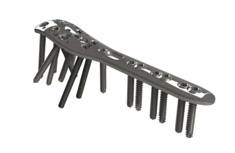
One of the problems I’m having is reverse engineering parts that have holes that aren’t orthogonal to each other, like trying to build an automotive transmission adapter and match the spacing and placement on seven holes unevenly spaced around a half meter oval. I haven’t found a good way of doing this. I’ve tried taking a picture and autotracing it in inkscape, and also tried using something like an architect’s table with orthogonal slides that allow me to locate the top, bottom, and sides of pins in the holes. Both are really cumbersome. Is there a better way? Like, in what I assume is a fracture plate in the article with all the screws sticking out of it: if you need to duplicate the location of all those holes to within 0.1mm, how do you do it?
I was hoping he was going to use that medical device as an example. Replicating that would be a challenge similar to something I am working on now.
For trans adaptors i’ve used a simple old method of making a pattern of card stock. Use thin flat stock, tape or rubber cement to temp hold against flange. You can usually locate any shaft hole so the paper slides up to the flange. Tape or glue stock to flange, take a ball bearing slightly larger than bolt holes and place it on the card stock over the hole and tap the bearing with a hammer to cut an almost perfect hole. Slide in bolt to keep in register if needed and keep going around. If pins are in the way you can tap on edges of pin over the card stock to cut that hole or you could drill a tight fitting hole in a piece of scrap and drive it over the pin and card like a hole punch. Now you have a flat pattern to work with directly or take measurements off however you like.
OK, I guess by “simple” I mean easier than trying to measure and locate over relatively large distances with no great reference points.
Use polar coordinates for the holes?
I take photos with my steel ruler regularly. Insert the photo in cad and scale to a line drawn at the correct length. Trace away..
Don’t forget to use the maximum optical zoom available to minimize distortion!
How do americans cope these days?
Still measuring in inches when their manufacturing base in China uses metric for everything.
Build American, that’s how. LOL. Truth be told told though, American Machine shops use Metric already and have been for decades.
Duh, we use both, just like the article does. And the Chinese use inches when we say to use inches.
For everybody suggesting tracing a picture or scan, check out Henner Zeller’s excellent Augenmaß:
https://github.com/hzeller/augenmass
Sometimes I’ve only had brief access to an object (for example, something is disassembled, but needs to be put back in service). So a few tricks I’ve learned:
(1) Take plenty of photos. (a missed dimension can often be accurately reconstructed from other dimensions in the photo).
(2) Stick a ruler in the photo. (in the same plane as the part if possible)
(3) Document EXTRA dimensions. (industry frowns on superfluous dimensions, but if you’ve made a mistake, recording similar dimensions for both directions, can be a valuable check).
I use Photoshop to get measurements from pictures. The perspective warp tool would work very well to straighten up the radio to get measurements using the ruler tool. If folks are interested, I can write up how I’d do the radio. It might even make a good follow-up article on Hackaday (hint hint hint).