Smart Ruler Has Many Features

For those of us who remember old ball mice, they were a lot like modern optical mice except that they needed to be cleaned constantly. Having optical mice as a standard way of interacting with a computer is a major improvement over previous eras in computing. With extinction of the ball mouse, there are an uncountable number of cheap optical mice around now which are easy pickings for modern hacking, and this latest project from [Vipul] shows off some of the ways that optical mice can be repurposed by building a digital ruler.

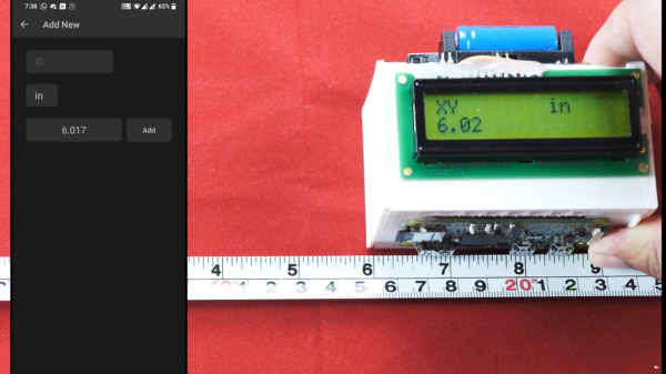
The build seems straightforward on the surface. As the ruler is passed over a surface the device keeps track of exactly how far it has moved, making it an effective and very accurate ruler. To built it, the optical component of a mouse was scavenged and mated directly to a Raspberry Pi Zero W over USB. Originally he intended to use an ESP32 but could not get the USB interface to work. [Vipul] was then able to write some software which can read the information from the mouse’s PCB directly and translate it into human-readable form where it is displayed on a small screen. The entire device is housed in a custom 3D-printed enclosure to wrap everything up, but the build doesn’t stop there though. [Vipul] also leveraged the Bluetooth functionality of the Pi and wrote a smartphone app which can be used to control the ruler as well.

While the device does have some limitations in that it has to make contact with the object being measured across its entire length, there are some situations where we can imagine something like this being extremely useful especially when measuring things that aren’t a straight line. [Vipul] has also made all of the code for this project publicly available for those of us who might have other uses in mind for something like this. We’ve seen optical mice repurposed for all kinds of things in the past, too, including measuring travel distances in autonomous vehicles.

Continue reading “Smart Ruler Has Many Features”

Machinist’s Accuracy Vs. Woodworker’s Precision

There are at least two ways of making parts that fit together exactly. The first way is the Cartesian way, and the machinists way. Imagine that you could specify the size of both the hole and the peg that you’d like to put into it. Just make sure your tolerances are tight enough, and call out a slightly wider hole. Heck, you can look up the type of fit you’d like in a table, and just specify that. The rest is a simple matter of machining the parts accurately to the right tolerances, and you’re done.

The machinist’s approach lives and dies on that last step — making the parts accurately fit the measure. Contrast the traditional woodworker’s method, or at least as it was taught to me, of just making the parts fit each other in the first place. This is the empirical way, the Aristotelian way if you will. You don’t really have to care if the two parts are exactly 30.000 mm wide, as long as they’re precisely the same length. And woodworkers have all sorts of clever tricks to make things the same, or make them fit, without measuring at all. Their methods are heavy on the jigs and the clever set-ups, and extraordinarily light on the calipers. To me, coming from a “measure carefully, and cut everything to measure” background, these ways of working were a revelation.

This ends up expressing perfectly the distinction between accuracy and precision. Sometimes you need to hit the numbers right on, and other times, you just need to get the parts to fit. And it’s useful to know which of these situations you’re actually in.

Of course, none of this is exclusive to metal or wood, and I’m actually mentioning it because I find myself using ideas that I learned in one context and applying them in the other. For instance, if you need sets of holes that match each other perfectly, whether in metal or wood, you get that precision for free by drilling through two sheets at one time, or by making a template — no measuring needed. Instead of measuring an exact distance from a feature, if all you care about is two offsets being the same, you can find a block of scrap with just about the right width, and use that to mark both distances. Is it exactly 1.000″ wide? Nope. But can you use this to mark identical locations? Yup.

You can make surprisingly round objects in wood by starting with a square, and then precisely marking the centers of the straight faces, and then cutting off the corners to get an octagon. Repeat with the centers and cutting until you can’t see the facets any more. Then hit it with sandpaper and you’re set. While this won’t make as controlled a diameter as would come off a metal lathe, you’d be surprised how well this works for making round sheet-aluminum circles when you don’t care so much about the diameter. And the file is really nothing other than the machinist’s sandpaper (or chisel?).

I’m not advocating one way of working over the other, but recognizing that there are two mindsets, and taking advantage of both. There’s a certain freedom that comes from the machinist’s method: if both parts are exactly 25.4 mm long, they’re both an accurate inch, and they’ll match each other. But if all you care about is precise matching, put them in the vise and cut them at the same time. Why do you bother with the calipers at all? Cut out the middle-man!

How To Reverse Engineer Mechanical Designs For 3D Modeling

If you’re interested in 3D printing or CNC milling — or really any kind of fabrication — then duplicating or interfacing with an existing part is probably on your to-do list. The ability to print replacement parts when something breaks is often one of the top selling points of 3D printing. Want some proof? Just take a look at what people made for our Repairs You Can Print contest.

Of course, to do that you need to be able to make an accurate 3D model of the replacement part. That’s fairly straightforward if the part has simple geometry made up of a primitive solid or two. But, what about the more complicated parts you’re likely to come across?

In this article, I’m going to teach you how to reverse engineer and model those parts. Years ago, I worked for a medical device company where the business model was to duplicate out-of-patent medical products. That meant that my entire job was reverse engineering complex precision-made devices as accurately as possible. The goal was to reproduce products that were indistinguishable from the original, and because they were used for things like trauma reconstruction, it was critical that I got it right.

Continue reading “How To Reverse Engineer Mechanical Designs For 3D Modeling”

Precision Pantograph Probes PCBs

Electronic components are getting smaller and for most of us, our eyesight is getting worse. When [Kurt] started using a microscope to get a better view of his work, he realized he needed another tool to give his hands the same kind of precision. That tool didn’t exist so he built it.

The PantoProbe is a pantograph mechanism meant to guide a probe for reaching the tiny pads of his SMT components. He reports that he has no longer has any trouble differentiating pins 0.5 mm apart which is the diameter of the graphite sticks in our favorite mechanical pencils.

[Kurt] has already expanded his machine’s capability to include a holder for a high-frequency probe and even pulleys for a pick-and-place variation. There’s no mention of dual-wielding PantoProbes as micro-helping-hands but the versatility we’ve seen suggests that it is only a matter of time.

Four bar linkages are capable of some incredible feats and they’re found all around us. Enjoy one of [Kurt]’s other custom PCBs in his Plexitube Owl Clock, or let him show you to make 3D objects with a laser engraver.

Continue reading “Precision Pantograph Probes PCBs”