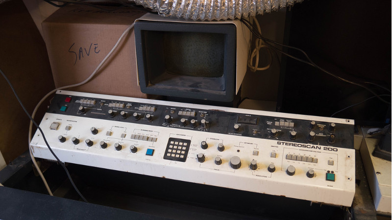
We don’t know about you, but when our friends ask us if we want to help them fix something, they’re usually talking about their computer, phone, or car. So far it’s never been about helping them rebuild an old electron microscope. But that’s exactly the request [Benjamin Blundell] got when a friend from a local hackerspace asked if he could take a look at a vintage Cambridge Stereoscan 200 they had found abandoned in a shed. Clearly we’re hanging out with the wrong group of people.
 As you might imagine, the microscope was in desperate need of some love after spending time in considerably less than ideal conditions. While some of the hackerspace members started tackling the hardware side of the machine, [Benjamin] was tasked with finding a way to recover the contents of the scope’s ROM. While he’s still working on verification, the dumps he’s made so far of the various ROMs living inside the Stereoscan 200 have been promising and he believes he’s on the right track.
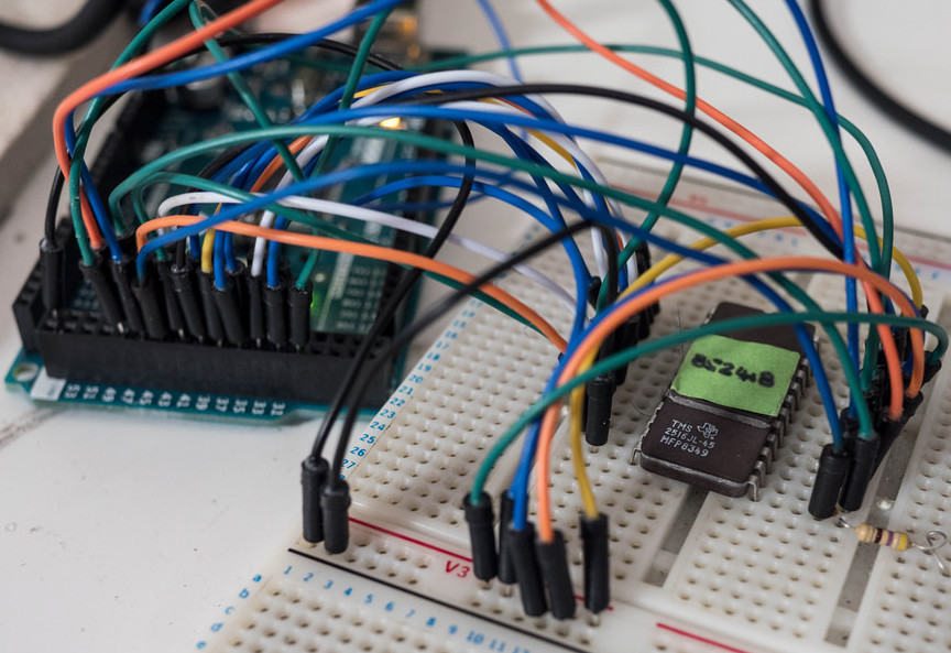
The microscope uses a mix of Texas Instruments 25L32 and 2516 chips, which [Benjamin] had to carefully pry out after making sure to document everything so he knew what went where. A few of the chips weren’t keen on being pulled from their home of 30-odd years, so there were a few broken pins, but on the whole the operation was a success.
Each chip was placed in a breadboard and wired up to an Arduino Mega, as it has enough digital pins to connect without needing a shift register. With the wiring fairly straightforward, [Benjamin] just needed to write up some code to read the contents of the chip, which he has graciously provided anyone else who might be working on a similar project. At this point he hasn’t found anything identifiable in his ROM dumps to prove that they’ve been made successfully, all he really knows right now is that he has something. At least it’s a start.
More and more of these older electron microscopes are getting a second lease on life thanks to dedicated hackers in their home labs. Makes you wonder if there’s ever going to be a piece of hardware the hacker community won’t bend to their will.


The contents of the ROM’s on the analog PCB’s are probably lookup tables with settings for ex. magnification, fine focus, medium focus etc etc. I have a Stereoscan 260 (also under reconstruction) and it uses something called “Optibeam”, a “program” (actually a lookup table) that controls the electron optics. It would be very interesting to compare the .bin’s.
Good luck with the restore :)
Interesting, I also have a Stereoscan, the 120 model, that I’m in the process of trying to revive. I opened up the console and was baffled at the odd point to point wiring with alligator clips I saw. I hope that you guys don’t encounter the same.
I was told c:1975 on good authority from a certified Cambridge technician in Melbourne, that at some stage the Cambridge development area was updated and they painted over some of the most important lens calculations that had only ever been written on the wall. Charming, but not really reassuring. The Americans were pushing a much more compact AutoScan at the the time, however we went with the tried and true British design anyway.
People out there finding SEMs in sheds, and I’m over here considering myself lucky if I see an old desktop PC on the side of the road…
Benefits of being in a region with a lot of tech and an active tech/hacker community: lots of interesting stuff. Drawbacks of being in a region with an active tech/hacker community: the interesting stuff tends to get glommed up fast, and those of us that can’t take weekdays off miss a lot.
Solution is to hook up with a good hacker space or group. Things may end up being communal or belonging to someone else, but they at least enter your life.
You could always move to Ghana
I was in the same boat when I was a kid. Small town, pre-internet. I could hardly find someone willing to give up an old clock radio. It could of been worse, I hear Ghana is pretty bad for finding surplus SEM’s.
I like the Arduino Mega method with code and details. Not sure what there are for manuals on this make and model.
I used to work with the second model Stereoscan, c.1973 Melbourne University Botany School. All analogue, no ROMs in that old girl. Advanced technology then was using Lanthanum Hexaboride emitters instead of Tungsten filaments. Best wishes with your project, they are very exciting machines to use.
I used and maintained a MarkII Stereoscan. It was mostly vacuum tubes with a few transistor modules. No computers at all unless you count the cam driven vacuum pump down sequencer. Good times…
I’d just have used an EPROMer to dump the ROMs. Considering the age, I’d have done it twice, once with the EPROMs running on 5V and once with a 1N4148 inserted into the Vcc line (resulting in the EPROMs running at about 4,3V). If both dumps are the same, great, if not, the one done with 4,3V is likely the correct one (*). For those I’d try 2 1N4148 in series for another dump.
(*) The way an EPROM cell works means that cells that seem to have lost their programming can still be read with a lower Vcc.
A 2516 is the same as a 2716 and a 2532 can be read as a 2732 with a little adapter.
My trusty old EPROG 27011 will read a 2532 directly.
Good to know. Thanks for sharing that! Is there any special trick to the 2532 adapter or is it just a pinout position swapping?
To read a 2532 you need /CS (pin 20) LOW, Vpp (pin 21) needs to be on +5V. A 2732 needs /OE (pin20) to be LOW and /CS (pin 18) to be LOW to be read. So you would just connect Vpp to Vcc on the 2532 and then either leave Pin 20 connected as is or use the signal on pin 18 for /CS, that depends on how your programmer handles things.
The only difference in pinout between 2532 and 2732 are the pins 18, 20 and 21.
I found the Unix ‘strings’ command to be the first thing I did with a ROM image. All the com port commands and help strings came out that way for easy hacking.
That assumes there’s machine code with UI strings present in the ROM. If it’s a look-up table for analogue circuitry, you’d see no such patterns.
Latest results up on github: https://github.com/OniDaito/SEM
Still not sure it’s correct but the setup is now there and easy to tweak to make sure we are getting something useful.
I’d love to chat to folks who read ROMs from old arcade cabinets and similar things, just to know the process a little more
I built an EEPROM programmer using a Mega 2560. It could download EEPROMs to SD card and then reload them to burn into a blank. I am no programming genius (I am trying to revive a Synertech SYM-1, and I have ROM images of the RAE Assembler and MS Basic. was going to burn them to put them on the board) but if you would like a listing I could email it to you.
Sorry the older EPROMs, not EEPROMs, their modern day grandchildren.
I used to work on the next line so when I was not busy for a while I had to calibrate the Stereoscan with poloroid film. Some one made a pin hole camera and took some pictures of us. I posted item this on my facebook as I am still in touch with the people who tested them. I remember raiding the bins for old boards that poeple could not fix but I think they were image analyser boards I still have the Eprom programmer in the loft never bothered to use it probably ran on Dos.
I worked in the Cambridge Instruments factory in the 1990s (or LEO E.M./Leica as it was by then), in the service/spares dept. We were selling 400 series (?) by then, but we were still supporting 100/200 and 360 series machines. I spent a summer catelogling and storing ICs, boards and countless other parts. Copying and filing drawings. Getting the PCBs modded. Happy days!
It’s Carl Zeiss (Coldhams Lane) now. My dad retired from there this year after 46 years, there’s a few of the old grey beards still there from the Cambridge Instrument days, as well as my boss in spares who fixed 100/200 machines. I’ll give him a shout, he might get a kick out of this.