Salvaging a beefy motor is one life’s greatest pleasures for a hacker, but, when it comes to using it in a new project, the lack of specs and documentation can be frustrating. [The Post Apocalyptic Inventor] has a seemingly endless stockpile of scavenged motors, and decided to do something about the problem.
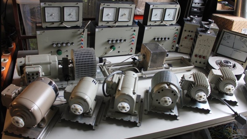
Once again applying his talent for junk revival, [TPAI] has spent the last year collecting, reverse-engineering and repairing equipment built in the 1970s, to produce a complete electric motor test setup. Parameters such as stall torque, speed under no load, peak power, and more can all easily be found by use of the restored test equipment. Key operating graphs that would normally only be available in a datasheet can also be produced.
The test setup comprises of a number of magnetic particle brakes, combined power supply and control units, a trio of colossal three-phase dummy loads, and a gorgeously vintage power-factor meter.
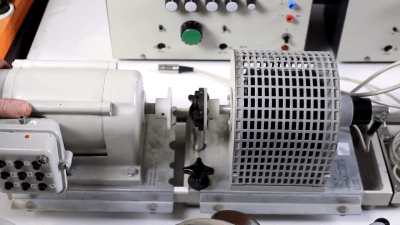
Motors are coupled via a piece of rubber to a magnetic particle brake. The rubber contains six magnets spaced around its edge, which, combined with a hall sensor, are used to calculate the motor’s rotational speed. When power is applied to the coil inside the brake, the now magnetised internal powder causes friction between the rotor and the stator, proportional to the current through the coil. In addition to this, the brake can also measure the torque that’s being applied to the motor shaft, which allows the control units to regulate the brake either by speed or torque. An Arduino slurps data from these control units, allowing characteristics to be easily graphed.
If you’re looking for more dynamometer action, last year we featured this neatly designed unit – made by some Cornell students with an impressive level of documentation.


Not really helpful for DIY torque testing. You can get max torque at zero RPM by connecting a spring balance to nut running on ballscrew eg: https://youtu.be/xP2ug_Zk4w8
[youtube https://www.youtube.com/watch?v=xP2ug_Zk4w8&w=480&h=270%5D
I find you can satisfactorily characterize DC motors entirely with just the winding resistance, back emf factor (kv, in rpm per volt) (the v should be a subscript) and some unit of torque per amp. I typically throw a sprocket on the shaft, and have the motor pull up a known weight (I loop the chain around the weight so it cancels itself out), apply a small voltage, and measure the speed and amperage. After you measure the winding resistance (with moderate amperage at stall gives more reliable results through the brushes) and no load rpm at full voltage (record the anperage and multiply by resistance to get the voltage drop within the winding and subtract that for the true back emf factor) you’ll be able to do some simple math and know exactly how the motor will behave under any condition (stall, overvoltage, moderate load, etc)
Or put some source of inertia on the motor. Start it up at full power while monitoring the current and speed. From the known inertia differentiate numerically the acquired speed data and torque pops out.
“Known inertia” isn’t really what you have though without taking apart the motor and measuring the rotor in detail.
If you added an inertia that was much larger than the motor you could probably ignore the motor inertia. Weigh the motor and use an initial load x100 larger for example.
AvE was working something similar for testing handheld power tools with a stack of brake rotors as the load. But he got caught up in the rigor of measuring the bearing losses etc.