Motor Test Bench Talks The Torque

Salvaging a beefy motor is one life’s greatest pleasures for a hacker, but, when it comes to using it in a new project, the lack of specs and documentation can be frustrating. [The Post Apocalyptic Inventor] has a seemingly endless stockpile of scavenged motors, and decided to do something about the problem.

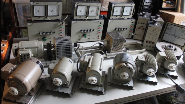
Once again applying his talent for junk revival, [TPAI] has spent the last year collecting, reverse-engineering and repairing equipment built in the 1970s, to produce a complete electric motor test setup. Parameters such as stall torque, speed under no load, peak power, and more can all easily be found by use of the restored test equipment. Key operating graphs that would normally only be available in a datasheet can also be produced.

The test setup comprises of a number of magnetic particle brakes, combined power supply and control units, a trio of colossal three-phase dummy loads, and a gorgeously vintage power-factor meter.

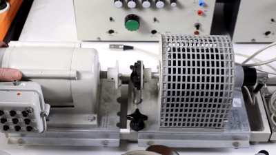
Motors are coupled via a piece of rubber to a magnetic particle brake. The rubber contains six magnets spaced around its edge, which, combined with a hall sensor,  are used to calculate the motor’s rotational speed. When power is applied to the coil inside the brake, the now magnetised internal powder causes friction between the rotor and the stator, proportional to the current through the coil. In addition to this, the brake can also measure the torque that’s being applied to the motor shaft, which allows the control units to regulate the brake either by speed or torque. An Arduino slurps data from these control units, allowing characteristics to be easily graphed.

If you’re looking for more dynamometer action, last year we featured this neatly designed unit – made by some Cornell students with an impressive level of documentation.

Continue reading “Motor Test Bench Talks The Torque”

Microsoft Secures IoT From The Microcontroller Up

Frustrated by the glut of unsecured IoT devices? So are Microsoft. And they’re using custom Linux and hardware to do something about it.

Microsoft have announced a new ecosystem for secure IoT devices called “Azure Sphere.” This system is threefold: Hardware, Software, and Cloud. The hardware component is a Microsoft-certified microcontroller which contains Microsoft Pluton, a hardware security subsystem. The first Microsoft-certified Azure Sphere chip will be the MediaTek MT3620, launching this year. The software layer is a custom Linux-based Operating System (OS) that is more capable than the average Real-Time OS (RTOS) common to low-powered IoT devices. Yes, that’s right. Microsoft is shipping a product with Linux built-in by default (as opposed to Windows Subsystem for Linux). Finally, the cloud layer is billed as a “turnkey” solution, which makes cloud-based functions such as updating, failure reporting, and authentication simpler.

Continue reading “Microsoft Secures IoT From The Microcontroller Up”

Roll Up Your Sleeve, Watch A Video With This Smart Watch Forearm Projector

We’re all slowly getting used to the idea of wearable technology, fabulous flops like the creepy Google Glass notwithstanding. But the big problem with tiny tech is in finding the real estate for user interfaces. Sure, we can make it tiny, but human fingers aren’t getting any smaller, and eyeballs can only resolve so much fine detail.

So how do we make wearables more usable? According to Carnegie-Mellon researcher [Chris Harrison], one way is to turn the wearer into the display and the input device (PDF link). More specifically, his LumiWatch projects a touch-responsive display onto the forearm of the wearer. The video below is pretty slick with some obvious CGI “artist’s rendition” displays up front. But even the somewhat limited displays shown later in the video are pretty impressive. The watch can claim up to 40-cm² of the user’s forearm for display, even at the shallow projection angle offered by a watch bezel only slightly above the arm — quite a feat given the irregular surface of the skin. It accomplishes this with a “pico-projector” consisting of red, blue, and green lasers and a pair of MEMS mirrors. The projector can adjust the linearity and brightness of the display to provide a consistent image across the uneven surface. An array of 10 time-of-flight sensors takes care of watching the display area for touch input gestures. It’s a fascinating project with a lot of potential, but we wonder how the variability of the human body might confound the display. Not to mention the need for short sleeves year round.

Need some basics on the micro-electrical mechanic systems (MEMS) behind the pico-projector in this watch? We’ve got a great primer on these microscopic machines.

Continue reading “Roll Up Your Sleeve, Watch A Video With This Smart Watch Forearm Projector”

Video Quick-Bit: Numitrons And Infinite Build Volumes

Majenta Strongheart takes a look at a couple of cool entries from the first round of the 2018 Hackaday Prize:

This is an infinite 3D printer. The Workhorse 3D is the way we’re going to democratize 3D printing. The Workhorse 3D printer does this by adding a conveyor belt to the bed of a 3D printer, allowing for rapid manufacturing, not just prototyping. [Swaleh Owais] created the Workhorse 3D printer to automatically start a print, manufacture an object, then remove that print from the print bed just to start the cycle all over again.

Check out this Numitron Hexadecimal Display Module from [Yann Guidon]. [Yann] is building an entire computer, from scratch, and he needs a way to display the status of various bits on a bus. The simplest way to do this is with a few buffer chips and some LEDs, but that’s far too easy for [Yann]. He decided to use Numitron tubes to count bits on a bus, from 0 to F. Instead of microcontrollers, he’s using relays and diode steering to turn those segments of the Numitron on and off.

Browse all of the entries here. Right now, we’re in the Robotics Module Challenge part of the Hackaday Prize, where twenty incredible projects will win one thousand dollars and move on to the final part of the Hackaday Prize where one lucky winner will win fifty thousand dollars for building awesome hardware. If that’s not incredible, I don’t know what is.

Adventures In Gas Filled Tube Arrays

Vacuum tubes are awesome, and Nixies are even better. Numitrons are the new hotness, but there’s one type of tube out there that’s better than all the rest. It’s the ИГГ1-64/64M. This is a panel of tubes in a 64 by 64 grid, some with just green dots, some with green and orange, and even a red, green, blue 64 by 64 pixel matrix. They’re either phosphors or gas-filled tubes, but this is the king of all tube-based displays. Not even the RGB CRTs in a Jumbotron can match the absurdity of this tube array.

[Muth] got his hands on a few of these panels, and finally he’s displaying images on them. It’s an amazing project that involved finding the documentation, translating it, driving the tubes with 360 Volts, and figuring out a way to drive 128 inputs from just a few microcontroller pins.

First, the power supply. These panels require about 360 Volts to light up. This is significantly higher than what would usually be found in a Nixie clock or other normal tube-based display. That’s no problem, because a careful reading of the datasheet revealed a circuit that brings a normal-ish 180 Volt Nixie power supply up to the proper voltage. To drive these pixels, [Muth] settled on a rather large PIC18F microcontroller with eight tri-state buffers. The microcontroller takes data over a serial port and scans through the entire framebuffer. All in all, there are eight driver boards, 736 components, and 160 wires connecting everything together. It’s a lot of work, but now [Muth] has a 64×64 display that’s green and orange.

You can check out a ‘pixel dust’ demo of this display in action below.

Continue reading “Adventures In Gas Filled Tube Arrays”

Litar: LiDAR air guitar

Litar: An Air Guitar Using LiDAR

This year, [Blecky’s] Hackaday Prize Entry is an air guitar which uses multiple LiDAR sensors to create the virtual strings. What’s also neat is that he’s using his own LiDAR sensor, the MappyDot Plus, an enhanced version of his 2017 Prize Entry, the MappyDot.

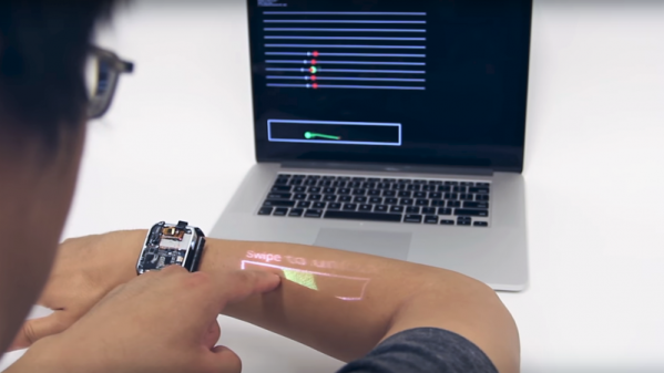
He uses a very clever arrangement of six sensors to get four virtual strings. Each sensor scans a 25-degree field of view. Three adjacent sensors are used to define a string, with the string being in the overlap of the outer two of those sensors. The middle sensor is used for the distance data.

For the chords, he started out using some commercially made joysticks but ran into some ergonomic issues. Also, the manufacturer was discontinuing the product, a no-no for an open source project. So he abandoned that approach and designed his own buttons. He came up with a PCB with a linear hall effect sensor and some springs on it. The button has a magnet attached to its underside and sits on the springs. That way he gets the press and can do vibrato as well.

He plans to use Bluetooth MIDI so that you can play the sound on a phone or laptop but for now he lights up an LED beside each sensor as you press the strings.

Retrotechtacular: Synchros Go To War (and Peace)

Rotation. Motors rotate. Potentiometers and variable capacitors often rotate. It is a common task to have to rotate something remotely or measure the rotation of something. If I asked you today to rotate a volume control remotely, for example, you might offer up an open loop stepper motor or an RC-style servo. If you wanted to measure a rotation, you’d likely use some sort of optical or mechanical encoder. However, there’s a much older way to do those same tasks and one that still sees use in some equipment: a synchro.

The synchro dates back to the early 1900s when the Panama Canal used them to read and control valves and gates. These devices were very common in World War II equipment, too. In particular, they were often part of the mechanisms that set and read gun azimuth and elevation or — like the picture to the left — a position indication of a radar antenna. Even movie cameras used these devices for many years. Today, with more options, you don’t see them as much except in applications where their simplicity and ruggedness is necessary.

Continue reading “Retrotechtacular: Synchros Go To War (and Peace)”