
Levers are literally all around us. You body uses them to move, pick up a pen to sign your name and you’ll use mechanical advantage to make that ballpoint roll, and that can of soda doesn’t open without a cleverly designed lever.
I got onto this topic quite by accident. I was making an ornithopter and it was having trouble lifting its wings. For the uninitiated, ornithopters are machines which fly by flapping their wings. The problem was that the lever arm was too short. To be honest, as I worked I wasn’t even thinking in terms of levers, and only realized that there was one after I’d fine-tuned its length by trial and error. After that, the presence of a lever was embarrassingly obvious.
I can probably be excused for not seeing a lever right away because it wasn’t the type we most often experience. There are different classes of levers and it’s safe to say that most people aren’t even aware of this. Let’s take a closer look at these super useful, and sometimes hidden mechanisms known as levers.
Levers Are One of the Oldest Mechanisms
Technically speaking, levers predate humanity. You find them in biology — your forearm is a good example which I’ll go into later in the article.
When it comes to man made mechanisms, levers are suspected to have been used as long ago as Ancient Egypt for lifting large block and obelisks but the earliest writings of their working principle come from followers of Aristotle and from Archimedes, both dated around 300 BC. Archimedes gave this static description of it:
Magnitudes are in equilibrium at distances reciprocally proportional to their weights.
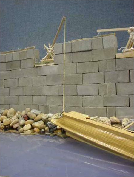
He also famously said, “Give me a place to stand on, and I will move the Earth.” Putting this into practice, he’s reputed to have devised a defensive weapon called the Claw for fighting off ships attacking city walls. Historical accounts seem to describe a crane sitting on the wall which lowers a grappling hook onto attacking ships and lifts them out of the water, capsizing or sinking them.
Lever Principles
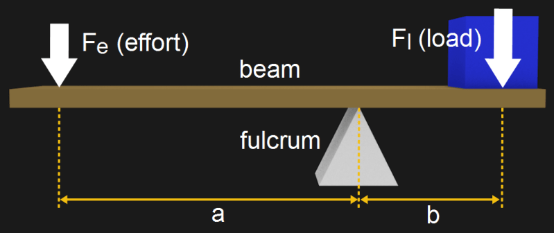
As shown here, a lever consists of a beam which pivots on a fulcrum. A force, called the effortFe is applied at some distance a from the fulcrum. And a load Fl exists at some distance b from the fulcrum.
The law of the lever states that:
The ratio of the force at the load to the effort force is equal to the ratio of the distances of those forces from the fulcrum.
Mathematically, it can be stated as:
MA = Fl/Fe = a/b
MA stands for Mechanical Advantage and is a measure of how much the force is amplified. The formula shows that if length a from the fulcrum to the effort is greater than length b from the fulcrum to the load, then the mechanical advantage will be greater than one.
Note that we’re not talking about free energy here. The power input is equal to the power output, ignoring losses due to friction, wear, and bending of the lever beam. Power is force multiplied by velocity and they differ proportionately from each other. If a > b then the load will move more slowly than the point where the effort is applied (which must move a greater distance in the same amount of time).
Classes of Levers
Levers can be arranged in different ways and are described in three classes, all of which follow the law of the lever.
 Class 1 Levers
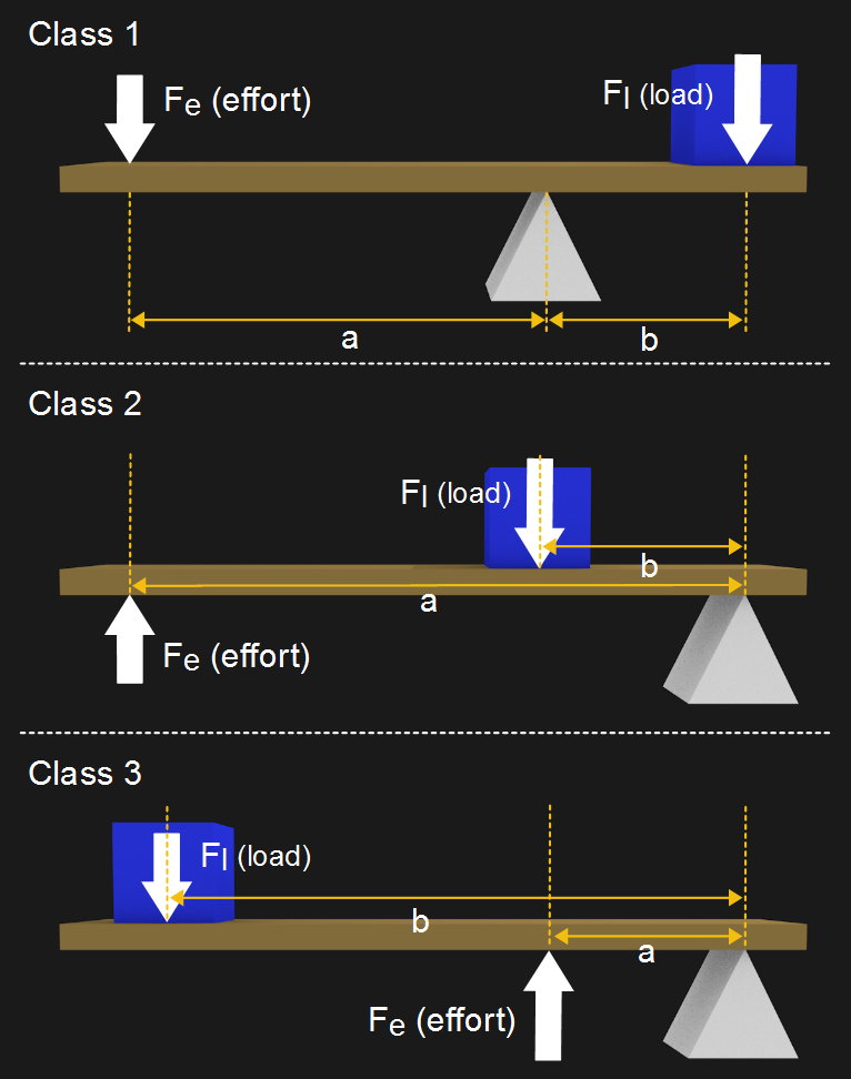
Class 1 is perhaps the most familiar. Examples of that are a seesaw, a crowbar as well as any time you’ve picked up a stick and placed it on a handy pivot point to lift something heavy at the other end of the stick. A pair of pliers are class 1 levers which we use very often but rarely recognize them as such.
Class 2 Levers
With a Class 2 lever, the fulcrum is moved to one end of the lever, with the load in the middle and the force at the other end. Every time you pick up a wheelbarrow you use a class 2 lever, with the wheel’s axle is the fulcrum.
Class 3 Levers
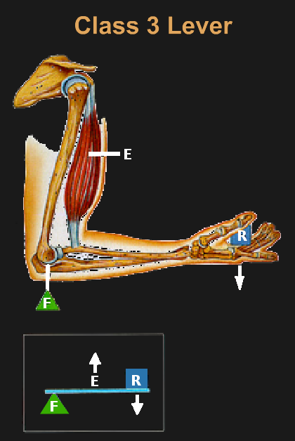
The arrangement of the class 3 lever can be the most difficult to visualize. The fulcrum is still at one end of the lever, but the effort is now in the middle, with the load at the opposite end. It’s harder to think of everyday class 3 examples but we’ll see three of them below. When we look at an exoskeleton arm, a human arm, and a rubber band driven ornithopter wing we’re viewing class 3 levers.
James’ Exoskeleton Levers
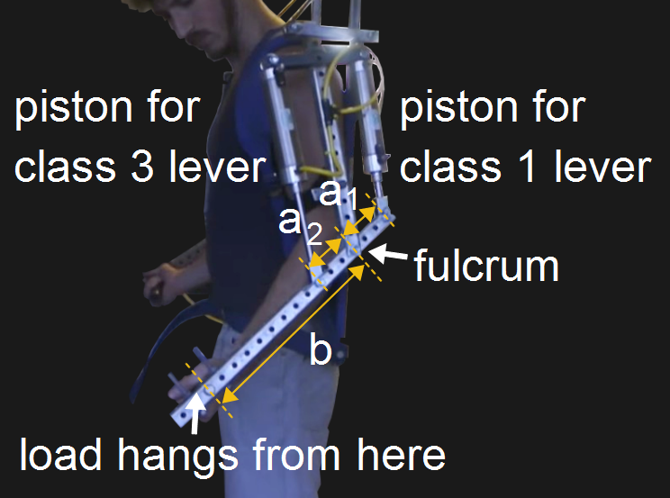
I searched for a great example of a lever in a hacker made project and came up with a great one by our very own [James Hobson]. He built an exoskeleton with arms for lifting heavy loads. Interestingly, each arm contained both a class 1 and a class 3 lever.
The arm is actuated by pistons. The main difference between class 1 and class 3 levers is that the load and the fulcrum have been switched. Here you can see that the location of the rear piston creates a class 1 lever, the location of the front piston creates a class 3 lever. You can see him use the rig to curl a 170 pound barbell.
Levers In The Human Body
With all its muscles, bones, and joints, it should be no surprise that the human body makes abundant use of levers.
However, they’re not always used for mechanical advantage. In the case of lifting a load by raising the lower arm and using the elbow as the fulcrum, the effort is provided by a muscle in the upper arm. This muscle is attached to the lever (the bone) very close to the fulcrum, meaning that a is short compared to b, which extends from the fulcrum to the load in the hand (in the diagram, R stands for Resistance). Therefore the mechanical advantage a / b is less than one.
Instead, the benefit here is that a small movement of the bone at the muscle produces a large movement at the hand. This makes for a compact and agile arm which can be useful in tight spaces. A lifting muscle which instead extends from the shoulder to near the wrist would get in the way much of the time. Note that James has done a similar thing with his exoskeleton arm, though he added the second piston to push while the other pulls/lifts.
The Ornithopter’s Lever

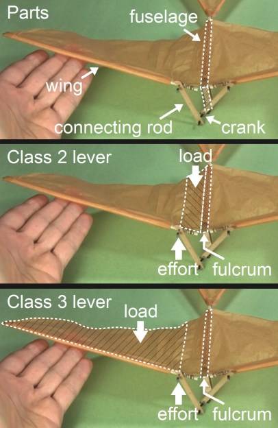 The typical rubber band powered ornithopter has a fuselage running down the middle that acts as the main body to which all the parts are connected. At the bottom of the ornithopter’s fuselage is a crank which is turned by a twisted rubber band. Connecting rods connect the wings to the crank. Turning the crank raises and lowers the wings through the connecting rods. This raising and lowering can be seen clearly in the animated GIF.
Looking at the diagrams, the fulcrum is in the middle of the ornithopter, at the top of the fuselage. It’s there where each wing pivots as they flap up and down.
The load is actually the air pressing on a wing membrane as the wing is pushed up or pulled down, though my issue was most evident when pushing up.
The effort is applied from below, where the connecting rods connect to each wing.
The non-obvious lever in my ornithopter turned out to be a combination of two different classes of levers, a class 2 and 3 lever, both of which exist in each wing.
Class 2 Lever
The class 2 lever is the section from the fulcrum to where the effort is applied by the connecting rod connected to the wing. The load which makes it a class 2 lever is the air pressure on the section of wing extending back between those two points. This fits the definition of a class 2 lever because the load is in the middle, between the fulcrum and the effort.
Class 3 Lever
The class 3 lever is again formed by the fulcrum and the effort at the connecting rod, but the load is the air pressure on the wing on the side farther from the effort in the opposite direction of the fulcrum. This fits the definition of a class 3 lever because the effort is in the middle, between the load and the fulcrum.
Seeing Levers Everywhere
So while levers don’t always stand out, they are found in a large number of places. That’s doubtless due to how useful they are. We’d like to hear in the comments below where you’ve used levers or which surprising places you’ve found them in.


Wow, I learned something new here that I had never even thought about. Thanks.
It’s basic physics, but I can think of an example of levers that few realize are levers – gears are basically spinning levers.
We even have economic levers. :-D
Such as…
https://www.unilever.com/
B^)
Yes, that is exactly right. So are car engines.
Nearly all mechanical machines reduce to levers and ramps. It’s pretty incredible, really.
Simple Machines they used to be called.
Again I am in debt to my parents for buying me the Great World Encyclopaedia of Science for my First Communion. The Catholicism did not last, but the explanation of the three classes of lever did, along with many other things. Incidentally the book also explained how a wheel can be considered a type of first class lever, in which infinitely many first-class levers surround the fulcrum!
And people keep buying huge tyres for their 4×4 and wondering why the driveshaft snapped… you’ve just made a bigger lever dude!
The expectation that drive line components behind the transmission be about to handle the the torque provided by transmission shoulddn’t be an unreasonable expectation. While the tires are a factor it’s the penny pinching engineering on the part of the truck manufacturer is the real reason behind any failures of stock components, not any bigger lever This of course there are no engine modifications that would increase the torque available.
GradeSchool-a-Day!
An common automotive engine hoist should be a class 3 lever.
cLever!
very cool. But it would be nice to see the mathematical formula of a and b on these three functions.
“don’t assume that people are stupid” is a nice rule to have. I wonder how this concept transferred
to pinions and gearing? Food for thought! ;)
Here’s a lever example from a really neat exhibit from my trip out west to pick up some maker related kit: https://www.facebook.com/photo.php?fbid=2548961361832317&set=rpd.100001554345519&type=3&theater
Where’s New Meico?
Is that something like new Geico?
B^)
Yeah, girco with lose wooden shoose is getting disturbing. I’ll edit. (▀̿Ĺ̯▀̿ ̿)
Any relation to Andy?
Griffith?
thanks for this information i have complted in physics i will help this post in my subjects thanks alot again
Can you do a “Mechanisms” article on Latches? Like over-center latches? I’ve looked for a long time and have never seen a concise explanation on how they work or how to design one (say for 3D printing).
That’s another good example of a class 2 lever. One of the design requirements there is that either the two pieces being latched together or the drawhook of the latch itself must have some elastic give. Notice how the lever moves the drawhook axis over the fulcrum, giving it the “over-center” name. Once it reaches a certain point, the elastic or spring is trying to pull the drawhook axis through the fulcrum instead of around it, causing the latch to lock in place. You could design this with a 3d printer by using a metal spring, or by cleverly making a plastic spring (a leaf spring perhaps?) by experimenting with different shapes through trial and error.
Of course there are tons of different types of latches.
http://www.jet-tek.com/camloc-latches-selection-guide/TL5.jpg
http://www.jet-tek.com/camloc-latches-selection-guide/TL4.jpg
The lower example pictured might be a good candidate for a 3d print design. Notice how the draw hook is a broad, curved shape–functioning as a spring. The lever pulls it taught and that tension holds the latch. You could make a similar leaf spring on an fff printer, but make sure it’s thick enough to be strong, thin enough to yield a proper amount, and the layers are printed in a way so they don’t cross the spring and make weak points. Likely printed as if that drawing was a view above the print bed looking down. You could print a few variations of different thickness on the same bed and swap them out, then make a one-piece design that prints pre-assembled once you’ve found the right spring.
I appreciate the illustration. What I’m mostly in the dark about is when you don’t have a springing part, but one part need to go past center to lock. (Consider the mechanism that makes Vice-Grips work.) If tolerances are at 0, then the mechanism won’t pull over to work. If the tolerances are too loose, it won’t latch when pulled over. There has to be rules about how things need to be sized or spaced in relation to one another to make the latch work properly without a crapload of trial and error. A CAD designer told me how verbally about 30 years ago in very general terms and I can’t remember or seem to find this information anywhere.
Thanks for taking a moment to appreciate the lever… excuse the pun.
Points for using a picture from Drexel!
Class warfare!
The class 2/class 3 distinction always struck me as contrived, even in grade school, and rhe annoyance was due to the somewhat arbitrary assignment of load and effort labels. In a class 1 lever, you can swap effort and load and it remains a class 1 lever. With a class 2 lever, swapping effort and load transforms it to a class 3.
If you discard the arbitrary label of “effort” and “load” and just consider them as forces in equilibrium, then class 2 and class 3 levers are the same thing.
My hypothesised missing 4th Class Lever, the Dynamic Lever
https://youtu.be/6B2BUDeRVJk
Chris