Back in the 70s when I started getting interested in electronics, tons of magazines catered to the hobbyist market. Popular Electronics was my favorite, and I think I remember the advertisements more than anything, probably because they outnumbered articles by a large margin. Looking back, it seemed like a lot of ad space was sold to companies hawking the tools and materials needed for wire wrapping, which was very popular for prototyping in the days before solderless breadboards were readily available. I remember beauty shots of neat rows of small, gold posts, with stripped wires wrapped evenly around them.
To the budding hobbyist, wire wrapping looked like the skill to have. With a huge selection of posts, terminals, and sockets for ICs and discrete components, as well as a wide range of manual and powered wrapping tools, it seemed like you could build anything with wire wrapping. But fast forward just a decade or so, and wire wrapping seemed to drop out of favor. And today — well, does anyone even wire wrap anymore?
Where Inventions Were Born
Almost everything we take for granted in the modern world can trace at least some of its lineage back to Bell Labs, the invention factory in the New Jersey suburbs, and wire wrapping is no exception. While wire wrapping may not have been invented there — a good argument can be made that it started in the previous century with telegraph linesmen splicing and securing wires in the field — the needs of the telephone industry, particularly in the central office, propelled the development of tools and techniques that would make connections easier. Bell Labs and Western Electric, the manufacturing arm of AT&T, would perfect wire wrapping in the mid-1950s.
The idea behind wire wrapped connections is simple — make a tight, metal-to-metal connection that’s electrically and mechanically solid, and do it as rapidly as possible. Soldering seems like it would make more sense electrically and mechanically, but it takes time and skill to execute properly, and introduces problems of its own. Wire wrapping, on the other hand, allowed telco techs to make hundreds of connections quickly, with simple tools, and in tight spaces.
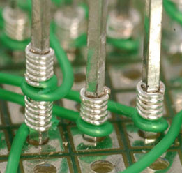
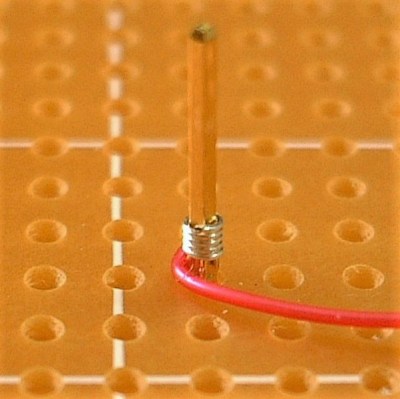
Specifics varied between applications, but the basics include terminals in the form of posts with a square cross-section and insulated solid wire. Insulation was stripped to a specified length, with care taken to avoid nicking the conductor within. The stripped wire was loaded into the metal bit of a wrapping tool, which was then placed over the post. A few quick turns of the bit, either with hand or electric power, wrapped the wire snugly around the post for about five complete turns and completed the connection.
Bil Herd did a great piece on the tools and techniques of wire wrapping a few years back, and this video shows what’s involved in making wire wraps:
Where Is It Now?
So what made wrapped connections so great? Part of it was the electrical and mechanical properties of the connection. A properly wrapped post would have at least one turn of the insulated part of the wire wrapped around the post, providing a degree of mechanical support that kept the conductor from breaking if the assembly were subjected to vibration. There’s also the benefits of the square post corners cutting into the round conductor twenty or so times along the wrap. Such connections are gas-tight, so oxygen is excluded from the mating surfaces and oxidation inside the joint is avoided. This also lets the wire and post form a cold weld, significantly reducing the resistance of the connection.
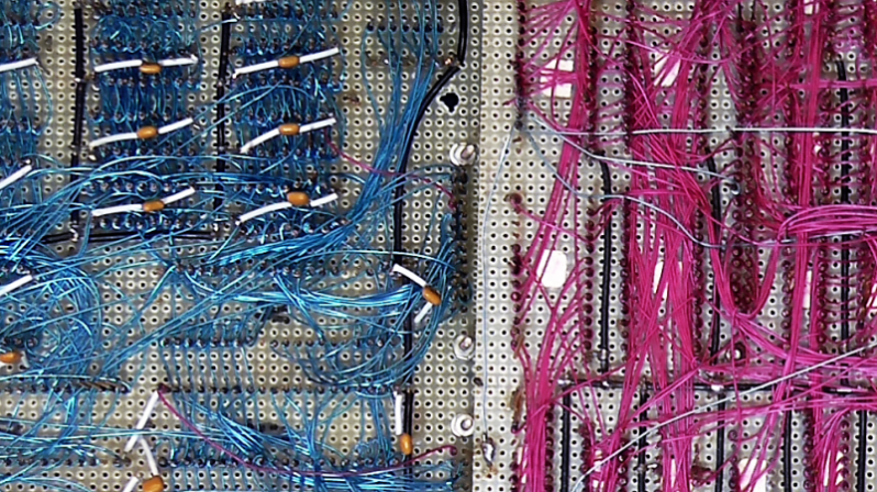
And yet we see precious little wire wrapping these days, at least judging by your tips and Hackaday.io projects. Why is that? Is it the rise of super cheap PCBs and the tools to design them quickly? Is it the increased availability and use of SMD components and the tools to properly handle them? Maybe wire wrapping is mainly used in the industry today for prototyping and has just lost favor in at the hobby end of the market? Or perhaps my perception is wrong, and wire wrapping is alive and well across the board, in which case maybe I should invest in some Kynar and a squeeze tool and get wrapping.
What’s your experience with wire wrapping? Sound off in the comments below.


Someone needs to design some SMD-to-WW breakouts so you can use this technique with modern parts.
What would be special about that? Breakout boards for using SMD parts with breadboards are already a common thing. Often they come without the pin headers soldered on. Wouldn’t one use one of those same boards for wire wrapping? Just solder on long, rectangular wirewrap pins instead of the usual short round ones.
I think the advantage would be in not using through-hole pins at all. If the adapters were single-sided and used SMD-mount pins for wrapping (facing up over the SMD parts), you could mount them on a solid ground plane (un-etched copper clad) for decent signal integrity. Just keep all the wires close to the plane, and it should have pretty decent performance. Like these but with wire wrap:
https://hackaday.io/project/12798-ugly-smd-adapters
http://www.proto-advantage.com/store/product_info.php?products_id=3400013
Many parts on digikey are there. This is strictly fly wire board. It doesn’t have proper layout. But it goes to pins for WW.
They are cheap and fast.
No they don’t, you can use surf boards avaible on Digikey.
I think the slow (?) death of wire wrapping is attributable to several factors including physical size, inductance of wires in high speed circuits, problems debugging circuits (look at the photos with hundreds of wires, all the same color), and the emergence of free PCB layout software and companies like OshPark that will make small runs of quality PCBs quickly and cheaply. I’d guess that it now takes less time and cost to design and build a board using a PCB than it would to do the same work using wire-wrap, and the PCB will be smaller and perform better.
Wire wrapping still has it’s uses if your in that valley beyond the frequency limitations of a bread board pushing you to blank vector boards but not ready for PCB boards. Avoidable if you spend more time preparing, but if you’re wanting to get down to it then it’s a weighing the options of wire wrapping and directly soldering your components. Just remember that the typical insulation on wire wrapping wire IS piezoelectric…which can be useful on it’s own for your creative hackers out there.
It think the demise was mostly due to wirewrapping being unable to keep up with the increasing clock and signal speeds used in commercial products – The market first dried up for wirewrap in military and minicomputers (which used wirewrap not just prototypes, but often in the shipping products), then personal computers weren’t long to follow. In the 70s and early 80s, successfully wirewrapping a DRAM bank could be done even without a lot of thought to terminations when dealing with processors that were running at a few MHz. In the early 80s the projects I worked on were all prototyped with wirewrap.
Noise coupling was a constant problem. It should be noted that even at it’s height, commercial motorized wirewrap guns were hundreds a pop and if you were prototyping a big project a 10″x7″ Augat board with its power distribution and ground planes could run $600. But if you were doing a dozen or so chips on perfboard using mailorder wirewrap sockets and a Radio Shack hand wirewrap tool and spools of wire you could do some nice projects. I built an 8085 system in my dorm room in 1979 that way. However, mixing in things like decoupling capacitors was never a good fit. If your design wasn’t almost completely pure digital, integrating wirewrap with analog components was messy.
As others had mentioned, even in the early 80s using wirewrap when trying to prototype elements such as video subsystems was a challenge. The physical size of wirewrapped prototypes using bipolar logic chips often meant running signal wires of a foot or more over or sometimes right alongside other high speed signals. Even using an expensive Augat board with its ground planes, power distribution busses, and support for including decoupling capacitors, you’d still get bit by noise and crosstalk.
By the end of the 80s processor and product clock rates and propagation delay demands had relegated wirewrap to comparatively low volume / slow speed niche digital products (and some hobbyists). Companies that had previously bought hundreds of wirewrap tools and hundreds or thousands of sockets a year to support their developers weren’t doing that anymore.
In parallel, PCB design and manufacturing tools and services had advanced to the point of wide availability for corporations and engineers in USA and Asia, though I think it wasn’t until the early 2000s when online PCB services became widely available at reasonably low cost for hobbyists (… and ‘makers’). My first small proto PCBs made with PC software were back in ~1989, but the per board cost was still pretty high (I recall about $20 each for 3″x4″). By 2004 I was able to get two ~4″x5″ two layer boards made and mailed for about $80 with about a 2 week wait, and , now you can get a handful of 2-layer boards for only a few bucks if you’re willing to take slow shipping.
Another factor to consider is that prototyping with wirewrap more-or-less tracks with the rise and fall of the use of small and medium scale logic.
As the mass market for wirewrap components and tools dried up so did the wide availability and reasonable costs of wirewrap components in the homebrew market. That said, wirewrap is still pretty good for 8085/Z80/6502 -era homecomputer projects, if using ‘real’ chips and keeping the I/O pretty simple (I.e. keeping away from things like zero-wait DMA and sound chips).
Given the high level integration of today’s prepackaged microprocessor boards (e.g. Arduino) with fairly low demands for additional logic or components to make an interesting project, wirewrap may again be feasible for prototypes you want to keep. But for most folks, the prototype role is satisfied by the true prototyping survivor of the 70s to early 80s wirewrap era: The solderless breadboard… and maybe some perfboard for analog. — then getting a PCB made.
Size is a biggy. I don’t see anyone doing an iPhone this way.
I’m sure, someone will see that as a challenge to be overcome…
The Wire Wrap Phone Kit comes with everything you need to build your own smart phone! One 4’x8′ sheet of pegboard, 200k pins, 15km of wire and a deep cycle lead-acid marine battery!
and the rotary dial mechanisms are becoming harder and harder to source …
there are machinists among us, are there not?
[herbert] you misspelled “masochist”.
Not too far off though: https://twitter.com/stroughtonsmith/status/990514307157889025
Back in ~1980 at General Dynamics all of our non-flyable systems were built this way. We even build a video processor that parsed video from the Evans and Sutherland image generators into the projectors used for flight simulation. To balance the complex terminating loads and keep the video clean an engineer build a gimmick capacitor from twisted wire-wrap wire. Then just trimmed the length with diagonal cutters while watching the video on a monitor. When it was clean, he stopped cutting. The big gotchas were always with inter-element capacitance and to be sure we never daisy-chained. Fun times, if you enjoyed strained vision, and working hunched over…
Similar recollections here – British Aerospace used wirewrap in production equipment because of the physical reliability. I love ww as a technique – so quick and easy. Hopefully we’ll be printing circuit boards using conductive ink using a flexible, toastable substrate on a regular basis in the not-too-distant future and home prototyping will be trivial ;-)
My father helped found a company in the early 1970’s that did wire wrapping on a large scale. Their main customers were the military. Not sure exactly what the appeal was. Some of it, I’m sure, was that there were small production runs that didn’t warrant doing a multi-layer PCB board. In other cases, I think it’s that the wire wrap had higher power allowances for things like radar systems or avoiding issues from power surges.
In the 80’s, I actually made some money wire *un*wrapping boards for his company. When one of the wire wrap machines screwed up (or someone messed up the layout), you had a useless board. The boards were, really, really expensive, so it was worth their while to undo the wiring to have another go at wrapping the board. They were generally unwrapped by hand (I’m not sure the automated machines could manage to unwrap a board… just wrap them). I got paid a good $25 to $60 (depending on the size of the board) to hand unwrap them. Not bad for a teenager in the early 80’s.
It was a pain in the butt, because you had to be sure all of the wire was removed from the posts. You could easily snap the wire as you unwrapped, leaving a few coils left around a pin. That would screw up the wrapping machines, resulting in having to unwrap it again, and starting the process all over (and you got yelled at, and potentially weren’t given any other boards to unwrap). And, needless to say, if you snapped a post, you were really screwed.
I remember in the end 70’s, beginning 80’s, Philips was placing telephone exchanges in Saudi Arabia (PRX-D exchanges). These were huge cabinets, with two processor boards, a bunch of I/O boards, some permanent storage, and a huge amount of Reed Relay switch boards. All boards were slid in the cabinets on rails, and at the backside were pushed into a bunch of connectors. And ALL these connectors were wire-wrap connectors. And everything was connected to each other through wire-wrapped wires. Huge amounts of wires and wire-wrapping.
It was actually not the PRX-D (using digital switches), but the PRX-A (using ‘analog’ reed relays).
You can get some glimpses in these videos:
https://www.youtube.com/watch?v=QgB0KSjC2zg
https://www.youtube.com/watch?v=IbTGVN2VMnQ
Wire wrap is pretty hopeless for today’s SMD components and anything moderately high speed. That’s why it is not used much anymore. Also the need for the special pins, sockets, etc. makes it difficult to use today because those things tends be difficult/impossible to find.
SMD parts, good point.
As for the high speed, that’s an issue when you get to 100 MHz clocks. I think you could wire wrap a basic microcontroller circuit without problems.
There was wire wrap in the ATC radar I worked on in the early 80’s. My memory of the SURAD secondary radar [made pretty symbols on operator scopes] is a tad rusty, but…
Part of the system had a 16MHz master clock. This was divided down into 16x 1MHz signals, each with 22.5 degrees of phase difference (16x 22.5 = 360 degrees). When building or repairing a control board, changing parts meant changing propagation delays, and sometimes required you to wire-wrap to a different clock phase to keep everything running.
Yeah, for slow stuff, It’s fine. I used a combination of wire-wrap and soldering (I did technically solder every connection, but I wire wrapped to make the majority of the initial connections) to create a custom keyboard. I laced the wires as well, just because I liked the idea of doing it that way. LEDs were powered by the heavier gauge wire, but all the wiring of the key switch matrix is done with a couple turns of my hand wire wrap tool, and were then soldered (since they weren’t full 20+ turn wraps). All the wires terminate with a Teensy microcontroller, or with a few proto boards with some LED driver or I2C stuff.
http://richfiles.solarbotics.net/eb/Keyboard75+1WireLacingFinal.jpg
Yup.
The answer to the question posed in the headline is: DIP packages went away.
Wire wrap, at least where I work, has been replaced by quick turn PCBs, like those from ExpressPCB.
Not a huge fan of building or modifying large wire wrap designs, though that was what we did as a matter of course at Data General back in the 80s
I use lots of DIP packages.
I wouldn’t use wire wrap because it is bulky and requires too much expensive equipment. Just adding posts for everything would be an excess of time and money. It would be simpler to just order a PCB! That part is true even if you’re still doing through-hole.
The reasons that service techs had were pretty good reasons, when equipment had to be wired instead of plugged. But these days techs would want connectors.
For prototyping it was an arbitrary choice that wouldn’t help or hurt your too bad, so lots did it that way, but these days there is just a huge difference in cost and result. It does look pretty, though.
I just leave this here…
i’m still using wire wrapping wires for proto, but not the way it is supposed to use, because i’m soldering it :) the nice thing is that i can clear one end of the wire and solder it and then i measure the wire and cut the other end, after i can melt the plastic away then with a help of a tweezers i can solder it to the destination, the wire itself is very good quality, it is even silver coated, so the soldering is very easy…
Wire wrapping wire is just perfect for jumpers and debug leads. I recently joined a company that was staffed with young engineers. I got a blank look when I mentioned wire wrap wire. They had never heard of wire wrapping, nor seen the wire. Now I have a lot of converts.
I was a summer intern for Westinghouse in the 80s, working for a department which tested military radar components, and all the test circuitry were on big (maybe 16″ x 16″) wire wrap boards. It allowed for a certain amount of re-workabilbity that PCBs can’t offer. Maybe they use FPGAs for this sort of thing today. The boards were sort of fragile, though, as I remember seeing a board that was mishandled somehow, and about 20 or so of the pins were sheared off in one corner.
Where those F16 and B1b radar test sets?
Possibly at Westinghouse in Linthicum MD?
If I remember correctly the AWACS electronics where all wire wrapped.
Jack
Definitely!
Certainly wirewrap is not going to be a good method for much of today’s high speed electronics.
But.. for those places that it could still be used I think part of the problem is probably the expense of wirewrap pins. I’ve long wanted to try building with wirewrapping and something I have noticed is that rectangular drawplates are a thing sold in jewelry making circles.
I’m thinking that maybe some day I could make my own wire wrap pins, perhaps I could find some sort of stiff brass wire and pull it through a rectangular drawplate myself. Then I could chop it into lengths to make pins.
or start a group buy with the gang here and ask around on alibaba
Or you could buy some off of eBay. https://www.ebay.com/itm/LOT-of-100-Wire-Wrap-Socket-Pins-from-early-1970s-gold-scrap-circuit-board-use/181575104901?hash=item2a46b83985:g:ukAAAOSwGWNUVYHU
Anyone else remember WireMaster, a program for taking a netlist and generation optimum wire wrap instructions? Even better, you could give it an updated netlist and it would generate rework instructions.
Used it 1984 …
Did GND and VCC in a 0.75mm2 copper grid.
Breadboarding with nice jumper wire kits have killed the quick and dirty end.
The cheap and easy gerber-to-board in small quantity has killed the higher end.
Between these you need breakout boards (and the male posts happen to be perfect for wire-wrapping), or DIPs.
You still need to design using a schematic, but layout is usually not that hard a second step.
I still use wire-wrap when I don’t want to use jumpers or need the shorter lengths or some other feature.
Also note the prices of each method, mostly in money but also in time and waste (e.g. soldering with cold joints or shorts).
You aren’t going to solder wires to discrete surface mount components, but even when they were through-hole, it was often cumbersome to solder point to point on a dense board (wirewrap could be very dense). When soldering, you had to solder, usually to a pad, then trim the lead almost flush.
Solderless plug-in breadboards are so cheap now. Also there are a lot fewer actual connections that most people have to make to do something valuable; you buy a small PCB with a processor, some GPIO, USB, etc,, and just plug it into a breadboard. The last wirewrapping I did was a Sophomore EE assignment where we built a simple computer with a 68020 (like some older Macintoshes), crystal oscillator (everyone’s favorite!) and some RAM.
I think the reason is a lot simpler than most suggested. I believe it’s the proliferation of cheap robotically-assembled dupont wires of any gender combination plus solderless breadboards. Now you just plug things together, and if you need to make it more permanent, then you reach for solder.
Wire wrap is slower than plugging and less secure than soldering, and given that soldering is a skill you need anyway, the need for wirewrap as an “in-between” connection technique just evaporates.
WW was dying long before the days ultra-dense SMD and auto-layout quick-turnaround cheap PCBs. For me, back in the day, inductance was the killer.
When the Intel 8080 was running at a clock speed of 2-3 MHz, wire wrapping worked OK for me. But 8-10 MHz was about my limit, except for very simple stuff. Beyond that, prototypes got flaky. Impedance matching on long-ish wire runs had to be tweaked individually. CMOS and TTL had different tweaks. For analog circuits, wire wrap connections were little tiny antennae. By the mid-1980s I was only prototyping low-speed peripherals in WW any more.
My old rule of thumb: if it’s digital and it works on a solderless breadboard (e.g., most Arduino peripherals) it will probably work in WW.
Just like PCBs, there are special techniques for high-speed wire-wrap construction.
With wire-wrap, you can equalize the length of every connection, so bus signals all have the same delay. You can use star, instead of daisy-chain topology. Cray supercomputers were wire-wrapped, in part because it was necessary for speed.
You can pack parts closer than possible with PCBs. Take the shortest path, rather than meander around components. Wires crossing is not a problem. In effect, you have a multilayer PCB with an “infinite” number of layers. This high packing density is why wire-wrapped was used on the Apollo AGC-1.
I worked on a minicomputer system with Motorola MECL-III logic. This was a family with sub-nanosecond gate propagation delays and 500 MHz clock speeds. It was all wire-wrapped. Each IC pin had two posts; one signal, and one GND. Twisted pairs of wire-wrap wire were used for the interconnections. They functioned as shielded transmission lines, to minimize noise and improve performance.
A few year back we need to make a custom controller with 49 SSRs. A guy I worked with took on the project. He found an old wirewrap board and stripped it of all the wires. Then he attempted to wire it up. He got hopelessly confused. When mistakes are made you need to remove the upper wires to get to the ones on the bottom. I offered to help. I designed a circuit board that was a fraction of the size and was easy to assemble. It worked the first time. I would have hated to try and troubleshoot that wirewrap board.
There is an order of assembly that prevents the daisy-chain problem when it comes to revisions.
Wirewrapping does give you a lot more flexibility as how how parts are placed, wires routed, etc., which is obviously important for higher-speed design. You don’t want long data lines running in parallel, etc. You can take advantage of “star” ground connections, etc. In those respects, it’s an excellent technique. It can get messy though!
” Why is that? Is it the rise of super cheap PCBs and the tools to design them quickly?”
Yes
” Is it the increased availability and use of SMD components and the tools to properly handle them? ”
Yes
The Bell System is a key in the wire wrap story. Wire wrap turns out to be a great way for telephone central offices to re-arrange jumpers when necessary to re-route connections. Bell Labs was a leader in reliability and the development of electronics in general and the Bell standard REQUIRED a lot of wire wrapping. What killed it off was the decreasing size of electronics and SMD put the nail in the coffin. BTW telephone central offices are still chock full or wire wrap.
It has lots of advantages like no heat, no solder and related bad joints or tools that need power. 25 or so gas tight electrical contacts per wrapped end and better vibration resistance than PCB’s – big PCB’s with heavy parts that is.
I worked in a Bell system Central Office for 5 years. I used to make hundreds of wire wrap connections every day. The main distribution frame was 252 vertical blocks long and 12 horizontal blocks high. Each block contained 100 or more pair of wire connections, depending on the style of block. It’s a very reliable way to make cross connections. The hard wiring on the back of the wiring blocks had been made decades prior and almost never had any issues.
Most of the hard wire static in house cabling was all wire wrapped and only once in 20 years did I experience one that had gone bad. There were wiring blocks that I worked on that were well on 40+ years old.
I made friends with one of the Western Electric Co. technicians that installed the lightening protection frame back in the 1970’s. The wiring on the back of that frame was all wire wrap and was still as good as the day it was installed.
These still exists here in Norway, but all new systems TLC-blocs from Krone.
The big problem with punch down blocks is that the punched connector pins get weaker and weaker over time. A wire wrap pin can get un wrapped as many times as you want without damaging the pins. In the CO that is important as customer move and get added and deleted. It is real easy to remove a single jumper without disturbing anything else. Like the Bell guy said above, the permanent wiring to the equipment and cable head never sees any impact or stress and survives forever. It also brings all cross connects in the building to a central location even if the actual equipment is multiple floors away. You never touch the equipment racks once they are installed and wired so there is little chance of messing up high density equipment racks. We used to wheel in prebuilt racks with the right cable lengths attached to them. Bolt the rack down and run the cables down to the distribution frames and plug them into the blocks (usually Amphenol Telco style connectors). We used wire wrap up to the 1.5 mbps DS-1 level. Above that we were in coaxial DS-3 connections and above that fiber cross connects.
The biggest reason I don’t use it that often is the cost of the sockets. You can spend more on a single 40 pin wire wrap socket than the rest of the components combined.
You can use standard sockets and pin headers on strip board.
https://cdn.hackaday.io/images/3707341461474730514.jpg
Pictured: Z80 CPU, FLASH, SRAM and video done in CPLD
But I cheat and do the routing in a CPLD which also replaces the smaller 74xx logic chips. This has the advantage that the same board can be reused for different chips and circuits without re-wrapping.
I see your photo, and my heart leaps,
though my mind whispers
nay, enter not into that sanctum,
for thou art mere mortal,
and canst be undone by the smallest of magic…
I like that. How are the headers anchored to the perf board? Are there pads to solder to for anchoring on the bottom side?
It’s strip board or vero board and there soldered underneath.
https://cdn.hackaday.io/images/5980561443851206577.jpg
Ingenious, and if it hasn’t been done already, deserves a Hackaday write up of its own.
Agreed! So cleanly done, and fast for prototyping.
CPLDs as glue logic and reconfigurable interconnects is really a GREAT idea!
I really like it! Back in 2000 or so, I built a small four legged walking robot. The controller was very simple, but I used sockets and headers to jumper between the control board and the “signal conditioning” board. When i discovered CPLDs I had always thought of replacing the second board with a CPLD to allow easier gait changes, by way of refreshing the CPLD with new logic. Never actually did it, but decided if I ever do, i’ll build a new robot that’s a little more mechanically capable. I might revisit the old one someday.
There aren’t many 5 Volt tolerant CPLDs around now.
The two series that I use are Xilinx XC95xxXL which are a 3v3 chip that is 5v tolerant and EPMxxx which are the same but the spec sheet says to use series resistors on the inputs. I never do that and I haven’t had problems with mixing with TTL.
On ebay you find lots of the smaller versions of the CPLDs. Of the EPM240/EPM570 (QFP100) you find lots of the EPM240. Of the XC9536XL and XC9572XL (QFP44) you find lots of the XC9536XL, I bought 100 of them.
If you run the CPLDs at 3v6 then they work well with 5v chips and have a good noise margin.
I was thinking of making some DIP boards with 4 of XC9536XL chips to get the pin count up and have lots of interconnects between chips for routing. That would give 144 macros which is enough for most simple things like VGA generation.
Yeah, Back in the mid 2000s, I had a lot of OT at my job, and just stockpiled XC95xx chips… I’ll probably never run out in my lifetime! XD
Just looked… I have:
30x XC9536 (PLCC)
70x XC9536XL (PLCC)
25x XC9536 (BGA)
33x XC9572 (QFP)
10x XC9572 (PLCC)
1x XC9572 (larger PLCC)
Hehe… Looks like we had similar ideas on how many XC9536 chips to get. The BGA chips are obscenely tiny. They were cheap as dirt, and back then I thought I might try using them for a project by soldering to them dead bug style… Under a microscope… These days, PCBs are so say to make, I’ll probably just try to come up with a board that’ll use them.
I also have a stack of PC boards that I was gonna try to reverse engineer. They each have an XC95108 with a bunch of drivers on the board meant to run all the blinking lights and displays on some manner of gambling machine. I got the stack of boards cheap, not knowing if I’d be able to do anything with them. Between weird connectors and the worry that the chips might not be reflashable… Well, they WERE from gambling machines, so who knows! :P
So yeah… I have a few of those chips!
I use it frequently, but not to the scale it was used in the past. Wire wrapping is a really easy way to attach multiple prototyping and breakout boards together for slapping a proof-of-concept project together. The most common header you’ll find on proto boards is 0.1″ square post, and wire wrapping is more reliable than those packs of socketed jumper wires. But wire wrapping will also work on non-0.1″ pins, LEDs and sensors, or the occasional DIP IC. For small SMD rework fixes or new proto board projects, I also use wire wrapping wire as the jumper of choice…it’s much more compact than larger hookup wire and much easier to strip than enamel wire. I have several miles of 30AWG Kynar here, and recently scored about 25,000 pre-stripped wire wrap in different colors and length…old stock from the Silicon Valley Electronics Flea Market.
I still use it for chaining together devboards/breakout boards as you can still fit two wires or so onto standard square-pin headers. Also the silver-plated kynar wire is great for PCB rework down to about 0.5mm pitch parts.
Wire-wrap is great when:
1. You want ONE of a particular circuit.
2. You don’t know if your design works; so expect to test, modify, and improve it.
3. You need high reliability and long life.
4. You’re a beginner, and want something easy to learn and needs minimal tools.
At the 2016 Vintage Computer Fair Midwest, visitors to our table built a classic 1802 Elf computer AT THE SHOW. 100% wire-wrapped; no soldering at all!
http://www.sunrise-ev.com/vcf-elf.htm
I drive by the old Netronics building every day. There’s still a little sign in the window! I’ve never stopped in, but I think whoever occupies that space now is doing mostly classic Landrover restorations.
Which is why we used it for our synth project in embedded computing last semester. There turned out to be other components we didn’t know about on some of our GPIO pins and we were able to just wire them up to different pins instead. I’m also using it now for simple breakout board projects like my EDtracker. I remain kinda bad at soldering and very bad at de-soldering. Wire wrap has vastly improved my quality of life.
I did a lot of wire wrapping back in the day. Both 26 and 30 ga. We used it for prototyping and some small production runs. In my mind the use of CAD to design PCB’s and the influx of really fast and inexpensive PCB tech made the big difference, and now with SMD and people fixating on small size. And wire wrapping had it’s issues, even back in the day it was not great for high frequency circuits and truly awful for anything with opamps.
Popular Electronics was a great magazine, but don’t forget Radio Electronics also. Then the merger into Poptronics.
Come to think of it, I don’t think I WW since the ’90’s either, but I’m sure I still have the tools. somewhere…
I thought EN merged with Nuts and Volts…
Some PCBs with config-jumpers… can’t always be properly configured with simple 2-pin jumper/shorting plugs. However, WW is a clean & sturdy way of making whatever whacky configuration you might need.
As as side note, the Apollo Guidance Computer was wire wrapped!
Back in the mid-90s I built a CLPS7110 based internet webcam for my university project (ARM720, same part as used in the Psion series 5).
Had to make a breakout PCB to get the 208 pins of the QFP out to wirewrappable pins, but then it was all wirewrap:
– SIM socket for FPM DRAM
– EPROM for boot
– SEEQ 8005 ethernet controller with local 64kB packet buffers
– “Parallel port” for attaching Connectix colour quickcam
Originally it ran my own OS & TCP stack, but I ported linux 2.0 to it after I graduated … very unique feeling running emacs on something you wirewrapped yourself!
Back then, Warwick university had the powered wirewrap guns and bins full of long-leaded parts so they were well set up for it.
One other note – you don’t need to use all the same colour wire! My supervisor recommended I use resistor colour codes for busses – eg D0 or A0 black, D1 brown, D2 red etc – and this helped significantly with me not cross-wiring things by mistake.
I just posted a small wire wrap project using mostly 35-40 year-old leftover parts:
https://hackaday.io/project/156536/log/145408-control-timing-board
Using modern parts, it’s what others have said: SMD & ExpressPCB have made it easier & cost effective not to use wire wrap. Oh, and I’ll throw in 3-hole-per-pad prototyping boards for through-hole part projects. This one uses three Vector 4615 Eurocards:
https://hackaday.io/project/27392-stupid-computer
To add to the list, all the connections on the rear-side of the PATRIOT radar array are wire-wrapped. Can’t recall if it’s a hundred thousand or a million, but it’s a lot. A sight to see on the production floor.
The problem for the hobbyist is the cost of equipment for wire-wrap. I am interested in using it as a technique as I never had a chance in the 80’s. I now have suitable sockets and wire but it took ages to get a wrapping gun at a reasonable price. New they are over £600 and the auction sites have them at £150+. It may be different in US compared to UK.
I know that wrapping pencils can be used and are reasonable in cost – but then I see no advantage then compared to point-to-point soldering – I want it for the busses in 6502/Z80 boards.
Just like soldering irons, wire-wrap tools are available all the way from $5 cheapies to $500 professional-grade instruments that will last a lifetime. Most people choose something in between (with hobbyists perhaps on the lower end :-)
You don’t need an electric wire-wrap gun unless you’re going to do a LOT of work. Use a decent quality hand tool instead. Radio Shack used to carry a cheap tool that wraps, unwraps, cuts, and strips for $10-$20 US. They just bought it from someone, so it’s still being sold (ebay #121926517172 for example). OK Tool made lots of hand tools that were very good in the $40-$100 range. I use this model (ebay #382384900513) BUT for #30 wire. Be SURE you get a tool for #30 wire — it’s by far the most common.
I still occasionally wirewrap when I need a high reliability but removable connection, essentially a high reliability jumper. Size is the main reason I don’t wirewrap prototypes these days. For smaller circuits, I use a combined stripboard and point to point wiring approach using soldered wirewrap wire for the point to point connections. For more complex circuits, I either make a single sided PCB or get a multi-layer board made. Even with fast turnaround, getting a PCB made can take time so wirewrap wire comes in handy for rework even down to 0.5mm pin spacing.
One of the worst ways to make permanent electrical connections, author still feels the need to claim it as american ingenuity…
Wire Wrap is more reliable than solder.
Lol
Well this obviously sounds very abstract today so I will elaborate.
As an “in practice” example, I once worked in a telephone exchange in the pre-computer era. We had about 11 isles of racks that had high density wire wrap back-panes into which modules were plugged. That’s millions and millions of wire wrap connections. On commissioning after installation there was one wire wrap fault. I found that fault when I worked there 20 years after the installation and there not another wire wrap fault for the remaining 15 years of service of the exchange before the technology was replaced.
The modules that plugged into these back-planes had soldered components and we many staff who’s full time job it was to fix these modules and a high proportion of the failures related to soldering.
The reason for this level of reliability is the chemistry.
As you would know, solder has flux and the purpose of that flux to remove oxidization and to a very small degree some other contaminants. Wire wrap does not use flux and following is the reason that flux is not required.
Wire wrap generally had silver coated wire-wrap wire and gold plated posts.
Both gold and silver start to oxidize as soon as they are exposed to the oxygen in air.
Gold is a soft metal and gold oxide is a poor conductor compared to gold but gold has a very high resistance to corrosion and oxidization.
Silver has the highest conductivity of all the elements. It has greater conductivity than gold or even copper. Silver oxide is also highly conductive as well.
The internal diameter of the wrapping tool is less than the diagonal width of the post plus twice the diameter of the wire which means that the wire is crushed into the corners of the post and not simply wrapped around the post.
This crushing action wipes the gold oxide layer and contaminants away from the corner of the post and also causes the corner of the post to penetrate through the silver oxide and contaminants of the wire and then directly into the non-oxidized silver. This in effect creates a direct silver to gold connection that is free of oxides and contaminants and that is why flux is not required. This connection is also gas tight so that no oxidization can occur within.
This direct contact between gold and silver forms a chemical bond often loosely referred to as a “chemical weld” or “cold weld”.
As the wire is wrapped around the four cornered post 5 or more times you get 20 or more of these chemical welds per connection.
In addition to this, wire wrap requires that you start with slightly less than one half turn of a turn of un-stripped wire.
The tensions that this causes results in the wire leading away from the post to form into a cross between a hyperbolic arc and a Nyquist plot.
As the wires are quite long the fundamental frequency of vibration is very low with reducing amplitude and therefore energy with each harmonic.
The higher energy fundamental vibration frequency is absorbed further away from the connection point or post where the radius of the arc is highest.
Each harmonic which has reducing energy is absorbed closer to the post with the lower energy harmonics being absorbed progressively along the arc of the wire as it approaches the post.
This creates a very high attenuation filter for mechanical vibration making wire wrap far more resilient to movement and vibration than most people would expect.
So while wire wrap is such an incredibly simple mechanical process that results are far better than expected.
The devil is the detail.
Was that a clever design, or a stroke of luck? Or perhaps WW started cheaper and more happy-go-lucky, had some initial problems and then gradual refinements and upgrades in methods and materials. Were there preceding ancestors to WW in electronic assemblies before DIP IC era?
I don’t know the full history of wire wrap so I’d imagine it started with a stroke of luck or genius then was progressively refined.
Early computers had terrible component densities and that resulted in long signal path and long signal paths meant slow clock speeds.
An early example would have been the Cray-1 supercomputer –
https://en.wikipedia.org/wiki/File:Cray-1-deutsches-museum.jpg
Here you can see the solution was to wrap the lower component density in a diameter larger then the higher contact density and smaller diameter to reduce signal path length. Also lots of parallelism.
This is the contact density problem that was solved with wire wrap.
I would assume that wire wrap not only predated DIP but also predated the integrated circuit.
In the valve era we used tag-strip which is kind of like a 3D version of Manhattan wiring.
https://www.radios-tv.co.uk/wp-content/sp-resources/forum-image-uploads/marc/2017/08/DSCF4205-Medium.JPG
We used to use a mainframe with a wire-wrapped backplane. It was getting old, and a primary failure mode turned out to be wires that were just a LITTLE too tightly resting against some pin that they weren’t supposed to be connected to. It worked fine for a long time, but 10+ years of vibration and insulation flowing eventually led to an occasional short, which we needed a miracle worker to find and fix (fortunately, we had one.) So while there are some nice properties of wirewrap, it has some interesting failure modes as well.
“Just Slit n’ Wrap”
Does anyone else remember the semi-automatic wire wrap machines from the 70’s? The machine positioned the tool over the correct pin and an operator made the wrap. We used these for large controller motherboards. Wire routing was hand done and loaded on to punched cards, one card per wire.
In 2004, while i did my vocational training with a major german Telephone company i used to prepare hundreds of these 3 connected wire wrap plugs for 2 Mbit/s PDH lines (legacy technology ????)
Long Long ago. Wonder If they are still operational.
I’ve been wire wraping for close to 50 years now, and still do so. When I layout a PCB, I stick adapters for the SMD parts I use around the sides of the PCB. From an 8pin SO-8 to 28 pin ssop and 80 pin PIC Micros . I have multiple colors of wires for signal, various power busses, etc. I keep my eye out for used and new w/w panels on ebay [the gold recover nuts have driven the prices up for the panels], as well as sockets. I use both the hand wrap tools as well as a electric w/w gun. It’s faster and easier for me to prototype on w/w, and then invest the time and expense for PCBs.
+1 Me Too! There’s a BIG difference between “Makers” now – and those of us who have been doing this prototype stuff for ages. WW has it’s place. It LIVES!
+1
My first wire wrap “pencil” was part of a standard techies repair kit. I never used it for a repair …but it did start me on the road to prototyping with wire-wrap. I still use wire wrap to cross connect 0.1 header pins (ie:- not real wire-wrap pins) between things like ESP8266 boards and displays (both of which come with the headers pre-installed), to make a quick connection without the flakiness of breadboard.
I’m still hoarding wire-wrap sockets and strip.
I’m running out of different coloured wire, though. ;-(
You can still find different w/w colors on Ebay
We used wire wrap in a few college labs (in 2012). It allowed us to reuse components. Yes a solder less breadboard can do that too but it can be a pain for more complex circuits and they tend not to hold together as well transferring them to and from class/lab.
We must’ve gone to the same school…go gators!
I started wire wrapping way back in… March 2018.
I realised that I had all these spools of wrapping wire for fine soldering jobs but had never tried using it for its intended purpose, so I got hold of a wrapping pencil thingy and gave it a go. And I love it! I’ve been soldering headers on modules and linking them with WW. Nothing is mission critical so I can make do with any issues but, so far, all is good.
Skimming the comments, don’t see the fact that the ubiquitous .025 square pins are standard wire wrap. Listen for the lovely click as the auto wrapper gun stops.
The majority of ICT manufacturers are using wire wrap as the only connection method for spring probes and board to board connections within the fixture. It is way more reliable than solder connections or other connectors. And reliability is the number one for mass production lines where one fixture will contact more than 1 million PCBs per year.
Also many PCBs in the automotive industry do not use soldered pin headers anymore. Especially modules which are exposed to mechanical stress and vibration will use just mechanically inserted (punched) pins, without being soldered.
https://www.youtube.com/watch?v=6GhSddLKsTU
No.
A good solder wont break/let go, just as a good wire wrap wont, that said, solder generally makes a better connection, especially considering were all ‘hackers’ at home, trying to stuff random hardware in random casings, and not people who have a assembly line that wire wraps internals that will never move or be touched again.
The reason wire wrapping still exists in some hardware is very simple, its easier to service if you can just pull of the connection without ruining the pads in the process.
Edit:
No @ “It is way more reliable than solder connections or other connectors”
You sure hate wire wrap. I guess you’ve never opened a cabinet to see 10,000 connections inside of a multi-million dollar computer where reliability was the utmost concern.
I have fond memories of wire wrapping repairs while working with air defense systems in the US Army. Nothing like tackling a wall size chassis containing miles of wire wrapped analog and digital beauty.
Chief
I can only speak for myself here, but, I never got into wire wrap because path routing is not easy to assign. Wires go where the tension pulls them. The tendency for paths to go close and parallel increases coupling (mutual inductance in high speed digital, mutual capacitance in high impedance analog) creating interference between circuit paths.
If I want a flexible, easy circuit with construction tradeoffs, I use solderless breadoards with a hard copper backplane, and cat5 / crosconnect wire for routing. The thicker gauge allows to sculpt the routes above the ICs, where I can shape the paths to avoid unwanted coupling. I don’t have to buy special sockets. Spools of cross connect wire are cheaper than spools of kynar by a factor of ~20.
Where I know the circuit well, I just make a PCB. SMT packages enable way higher speeds, and I can pour copper where I need it in huge, low inductance ground planes. By contrast, wire wrap tends to run grounds as wires, which become appreciable inductors to MHz frequencies after only a few cm in length. Ground bounce can become an issue, putting ghosts in the machine costing debug time the wrap process was supposed to save.
Above all, FPGAs. I love describing the hardware in verilog, and waiting 30 seconds for Lattice Diamond to compile my circuit on a $20 MachXO3-6900 board that runs at 100MHz, where protoboards and wire wraps become antennas, and where I can do six dozen high speed 74AC series logic ICs with one generate / for loop. Knowing HDL and FPGAs makes digital design process, and resulting circuits, both faster than hand wiring will allow.
Wire wrap makes beautiful circuits like typewriters make beautiful pages. Nobody would tell Jack London to use Microsoft Word, for the same reason I love FPGAs. Life’s short, use what you love.
I’ve hand-wrapped enough boards in my time and, in these days of fast cheap PCB proto services have no desire to return to doing that, however what I do miss is my supply of pre-stripped wire-wrap wire – I finally ran out recently and finding replacements is really hard, Digikey have some but it’s horribly expensive and comes in 50 wires per package.
Fortunately I found these in Huaqiangbei recently, in bundles of 500:
https://www.aliexpress.com/item/100PCS-32AWG-50MM-LONG-Tin-Plated-Breadboard-Jumper-Cable-Flexible-Two-Ends-PVC-Electronic-conductor-Wire/32854743647.html
For my part I typically do indeed wire wrap simple stuff after the thing survived being built, (and built all over again) on the breadboards.
I’ve got plans for either a simple R6502 system, or an equally simple CDP1802 (family members of) system. Also done that way of course. It just depends which gets shaken out.
I noticed that every CFL bulb has the wires from the PCB to the bulb wire-wrapped., while the rest is soldered.
It’s surprising and I assume there is a reason for it, related to the high voltage or heat changes or something.
On second tought, it may be because of the material of the wires, I think the wires coming from the tube might not be suitable for soldering so they solved that by using wire wrap.
Wire wrapped Amiga prototype:
https://pbs.twimg.com/media/CK29JtQUsAEP8xT.jpg
This guy is the undisputed god of prototyping:
http://elm-chan.org/docs/wire/wiring_e.html
He makes everyone else look really bad.
The processor cards from an Ericsson AXE 210 were a work of wire wrapping art… made by robots though, plus the odd bits and bobs by a person in the Ericsson factory we called Sunny Scunny.
So many comments on this i didn’t even want to say anything but i didn’t see what i used it for.
For BON (Bed of nails) fixtures we use wire wrap all the time. Even today.It makes it easy if the supplier or you designed it wrong and need to move a wire somewhere else. And its way stronger then having a bunch of connectors inside the fixture.
I had so many issues with the fixture that had connectors on the inside i ended up removing them all and wire wrapping back in place.
if i had a picture i could show i would attach. but i cant.
Is there any technique to make sure connectors (pins, IC sockets etc.) don’t fall off the board? Glue or just the wire wrapped as low as possible?
Hot melt Glue, Crazy Glue, or if the Perf Board you use has copper pads, a touch of solder at diagonal comers of the chip/socket.
I made a pseudo WW system using an old syringe with the needle rounded off at the tip. I fed enamelled wire down through it and could put a turn on a standard IC socket pin (which means cheap and low profile) and so on to the next connection. The enamelled wired was the type that melted on the heat of solder, so after “winding” I went back and the wires were actually soldered on. I found it worked really well for 8 bit busses on microcomputer designs around the 70’s. Draw back was the lack of colours, all brown! But it was great for busses as they were nearly all just simple parallel point to point. It gave all the other advantages of “multilayer”, correction of prototyping errors, but with the reliability of soldered connections and low inductance.
Didn’t think it was that special at the time, but hey maybe it was? I have tried using coloured WW wire to do the same recently but the plastic around the wire wrap wire is not friendly to the tip of the soldering iron, too acidic??
They used to produce those commercially (I still have the “pen” with the little spool of wire on the end somewhere and I probably also have a couple of 30+ year-old project boards with the little plastic combs which they sold to keep the wiring neatly bundled). The tip of the pens used to wear/melt through after a few milliseconds of use (well, seemed that way, anyway) and you needed to use a small diameter metal tube (a propelling-pencil tip in my case, rather than a medical needle) to fix it. It always seemed to be a lot more work than it was worth (which is why that pen is “somewhere”, but my wire-wrap tool is within reach on my workbench).