The real power of 3D printing is in infinite customization of parts. This becomes especially powerful when you combine 3D printing with existing materials. I have been developing a few simple tricks to make generic fasteners and printed connectors a perfect match for aluminum extrusion, via a novel twist or two on top of techniques you may already know.
 Work long enough with 3D printers, and our ideas inevitably grow beyond our print volume. Depending on the nature of the project, it may be possible to divide into pieces then glue them together. But usually a larger project also places higher structural demands ill-suited to plastic.
Those of us lucky enough to have nice workshops can turn to woodworking, welding, or metal machining for larger projects. Whether you have that option or not, aluminum extrusion beams provide the structure we need to go bigger and to do it quickly. And as an added bonus, 3D printing can make using aluminum extrusion easier and cheaper.
Everything is Built from Aluminum Extrusion
Aluminum extrusion beams are no stranger to these pages. We have a general overview of them and we have seen so many projects using extrusions, like satellite trackers, Rubik’s cube solvers, and automated drone charging stations. Many popular 3D printers have frames of aluminum extrusion as they offer higher strength and superior dimension tolerances than 3D printed plastic.
But creativity is quickly stifled by connector selection, as the vast majority of connectors in the catalog are for 90-degree joints of one flavor or another. Angled connectors are in the minority, and usually limited to a few angles like 30, 45, and 60 degrees. There isn’t enough sales volume to justify making connectors with angles that only a few people would ever use. This is where our 3D printer re-enters the picture, as a factory for low volume niche parts.
Custom Doesn’t Mean Hard
 Combining custom with stock allows us to design projects leveraging the strengths of each part: the aluminum extrusion provides generic structure, with the 3D printed plastic linking them together in a project-specific way. We’ve covered 3D-printing right angle connectors before (or in conjunction with zip-ties) but today we’re focused on 3D printing’s advantage for very precisely building arbitrary angles.
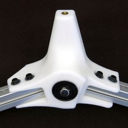
The CAD to design for these connectors is pretty simple. It is typically a matter of subtracting out a rectangular solid for the beam itself, followed by subtracting a few cylinders to create mounting holes for fasteners. Bolting to an extrusion on three sides (like the rocker arm example here) is usually strong enough for 3D printed plastic projects. This means we can often skip the “top” (relative to print bed) side for easier printing. Sometimes we’ll want that strength badly enough to deal with bridging or some other technique to give us that fourth side, but we’ll leave that challenge aside for now. The point is, that you can give this a try with minimum effort and adopt more of the technique as you get used to it.
An Example: Hard Angles Made Easy
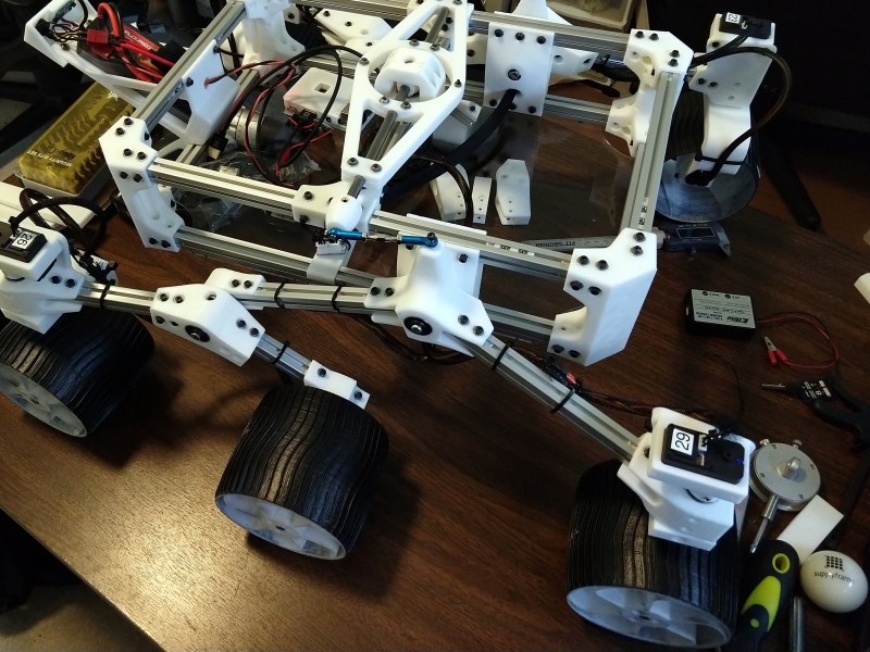
I’ve been working on a design for a rocker arm sub-assembly and it makes a perfect example of this discussion. It is part of the suspension system for a robot I’m building. The entire design is far too large to print as a single piece, so I divided the object into aluminum segments linked together by 3D printed parts. Here are the wireframe diagrams:
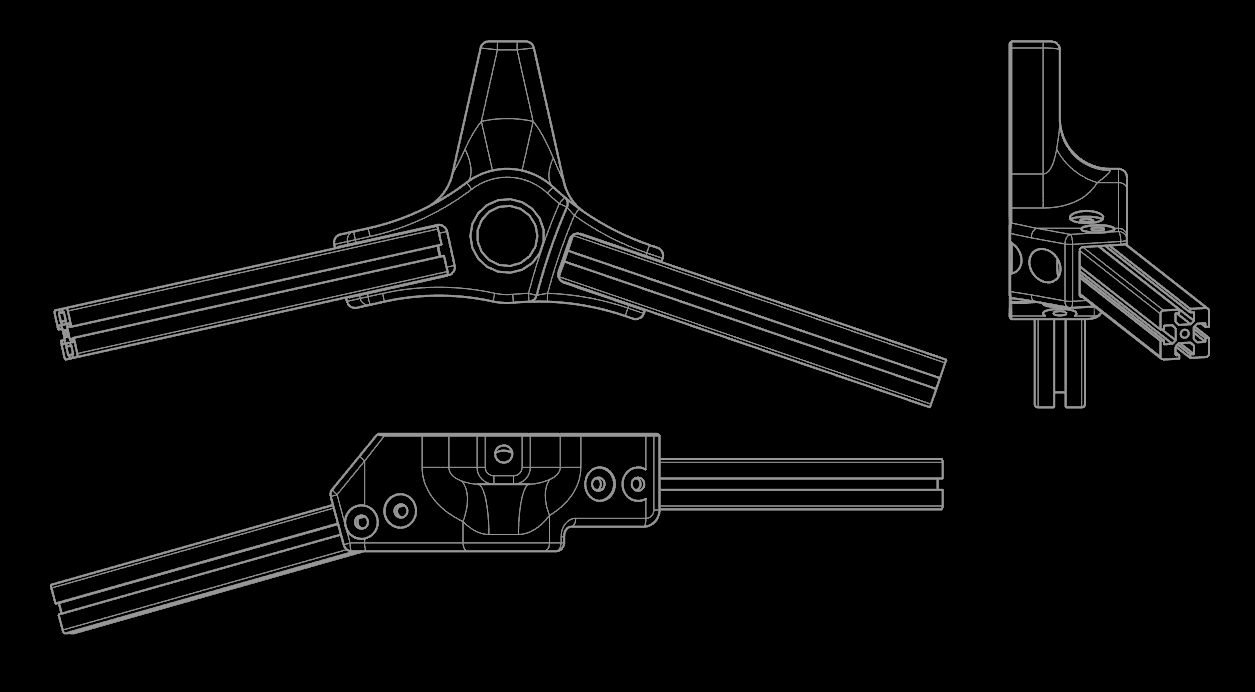
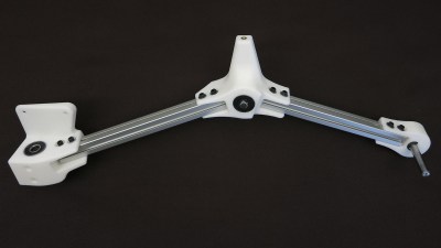
Look at the relative angles of these two extrusion segments — no extrusion vendor would stock connectors at these angles and if they did you still wouldn’t get a pair of bearings at its center and a mechanical linkage up top. Such project-specific details make this hub ideal for one-off 3D printing. As for the arms, we could spin up a 3D print job for two long rectangular blocks of plastic. But why? The only project-specific detail here is length, which can be cut far faster than an identical length of plastic can be printed, even if the cutting was done by a hand-held saw.
This article focuses on where the aluminum meets the plastic so I’m not going to go deep into the details on setting up your angle or removing the area for the extrusion. But it’s worth noting a few general 3D printing behaviors that strongly impact this construction technique. Select your layer orientation wisely — when printed parts are pushed beyond their limits, they generally fail by fracturing along layer boundaries. Use at least two fasteners along each axis, spaced approximately as far apart as beam width, to spread out workload. Using just one fastener turns that single point into a fulcrum multiplying forces on our printed parts, and we don’t want that.


One more point to consider is overhang when bolt holes do not align nicely with the print bed. We can help our printer bridge odd bolt head surfaces by creating a thin layer (2-3 print layer heights thick) covering the bolt hole which can be cleaned up with a drill after serving its purpose. These are easier to remove and consume less material than the typical solution of printing supports.
The Secret Sauce: A Replacement for T-slot insert, T-nut, T-whatever
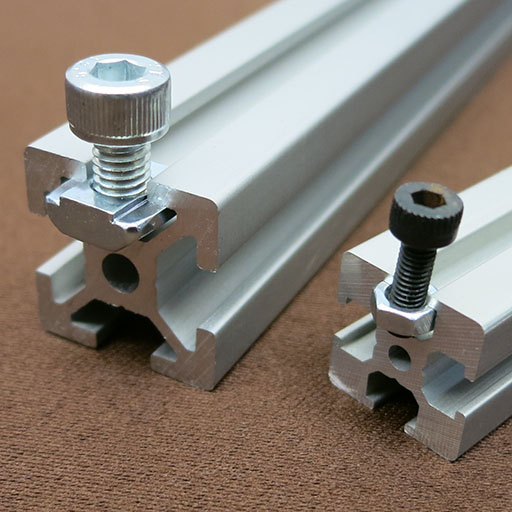
Once we have a project-customized connector designed and printed, we proceed to assembly where we face the other hidden gotcha of aluminum extrusions: specialty fasteners. Called T-slot inserts, T-nuts, or some similar name, they are shaped specifically to fit in the slot of an aluminum extrusion beam. They are also extremely expensive. Not necessarily in an absolute sense, but certainly relative to commodity hex nuts of similar size. Our rocker arm example is designed for 15mm Misumi 3 Series extrusions. Misumi offers several specialty nuts for this extrusion, the least expensive “economy” model HNSQ3 costs $8.28 for a bag of 100. In contrast, our trusty hardware supplier McMaster-Carr offers generic M3 hex nuts at $0.88 for a bag of 100. (Catalog #90592A085)
Before we give in to the temptation of a 90% discount, let’s do a quick review of what we trade off by using generic nuts. The first and most obvious barrier is that a particular extrusion beam’s profile might not allow a generic nut to be used. Second, a generic nut will not engage slot interior surfaces to the same degree as a nut tailored to the extrusion profile. This usually means we can’t torque the bolt down as tightly before something slips. Third, higher end specialty nuts provide friction against the extrusion, either by its shape, size, or an additional thin metal spring that holds the nut in place. Nuts that stay at position instead of sliding around in the slot eases assembly, translating into less time wasted and lower frustration for the assembler. Such labor savings can outweigh a specialty fastener’s cost.
For this rocker arm example, the first concern does not apply as Misumi 3 Series is tolerant of generic M3 nuts. Item number two — reduced fastener torque limit — is acceptable as long as it is still sufficient for what we need on a 3D printed plastic project. And item three — assembly convenience — is something we can get back with some clever 3D printing.
We now apply 3D printing’s strength (a factory for low volume, task specific objects) to generic fasteners in aluminum extrusion beams. Our technique employs a small tool designed specifically for the job. For starters, this tool has a little hump to act as a spring that helps hold its position in the slot. Then, because the tool is designed alongside the part it will be used with, we can design it with trays to hold generic nuts spaced exactly at the distance we need. And as an extra icing on the cake, we add a little hook to the end. This hook — designed to be exposed when hub is in place on the arm — allow us to fine-tune our position without having to take things apart.
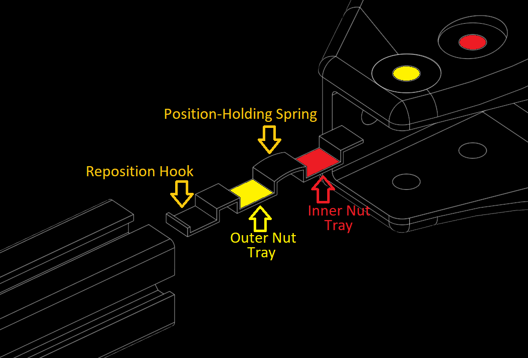
To fit within the narrow spaces left in the slot, the tool is printed as thin as possible: the width of our 3D printer’s nozzle. This also makes economical use of filament and it’s very fast to print, both attributes useful for a disposable item since this thin positioning tool can’t be removed once the bolts are tightened down. It is well worth the sacrifice, though, because it turns a frustrating exercise of aligning small fasteners into a trivially simple task.


Give this fastener method a try. I hope you find the technique useful and I look forward to seeing more projects that combine the strengths of 3D printing and aluminum extrusion beams into something that neither could do alone. If you are proud of your result, don’t be shy about letting us know via our tips line or maybe as an entry to our Hackday Prize. Happy building!


Isn’t plastic a bad choice here? Since the extrusion is rigid, doesn’t that mean the corners take a lot of stress?
We once printed some connectors and then stood at the end of a 1.5m length. No idea what the load was (high) and it didn’t falter even slightly. The printed plastic parts can be *very* strong, at least for most applications.
Aluminum extrusion doesn’t produce truly rigid structures even with the name brand metal brackets; there’s just too much slop in the tolerances.
For many things this isn’t an issue but if rigidity is what you’re after, and you have to use T-track extrusion, use epoxy or weld it. There’s some MIG wire that can lay a serviceable weld in aluminum if you don’t have access to TIG.
Watch on youtube for the time stamp to work or skip to 5:35 I highly recommend his whole 18 video playlist. I find myself coming back to it time and again.
https://www.youtube.com/watch?v=EeEhS3zmnDg#t=5m35s
Watched some time ago, I wish channel would be alive, a TON of info, highly recommended.
brazing is a decent option as well but yea t-slot + friction connectors ~= rigid, I end up drilling and tapping a lot of it
I disagree, a properly designed structure with aluminum extrusions can be very rigid. Well, as rigid as hollow aluminum can be. I have used a ton of it for various things (possibly quite literally)
This discussion needs a quantitative definition of “rigid”.
A hobbyist might wiggle a structure with light finger pressure and say it is rigid because they cannot feel it move.
A scientist, engineer or machinist might apply a load, measure the resulting deflection with a dial indicator in thousandths or tenths of thousandths of an inch (or a laser interferometer for more demanding projects) and say specifically how rigid it is. And be unlikely to start calling anything “rigid” that flexes more than e.g. an inches-thick cast iron machine frame, and they know that flexes under load.
When you say “rigid”, what specifically do you mean?
Here’s a link to a gokart (power racing series) that uses printed steering elements, including wheel mounts. While the end result was printed with the fiber-reinforced parts from a markforged printer, I believe the end result after a weekend of racing was complete success:
http://www.etotheipiplusone.net/?p=3713
very welcome article! More of this.
The little spring-a-majig that holds the generic nuts in place is a brilliant idea!
The Openbeam/MakerBeam XL systems are also 15mm and more commonly available than Mitsumi. OpenBeam has a slightly different profile (not smooth faces) but MakerBeam XL is smooth and has tapped ends. Cheap, too…I picked up 4x 500mm pieces for $30.
If you’re in Europe: here’s plain 20/20 12 x 50 cm for €20. No connection, satisfied customer.
(Note that the nut slots on these seem to be a little shallower than some. They work just fine with regular M4 nuts and bolts, though.)
But I don’t “get” why you have the (blue end) coupling rod at the top of the suspension.
To me it looks like it would just lock up the assembly.
The rod that’s at the other end of the coupling pivots in the center. This keeps the chassis’s pitch at half the angle between the two bogies. See here: https://en.wikipedia.org/wiki/Rocker-bogie
Thanks for the link, and correction!
I guess I’m not much of a “bogie-man”!
B^)
One point the article seems to overlook is that the OEM nuts, whilst expensive, can be _inserted into a track even when the ends are inaccessible_. In extreme cases, this can make the difference between being able to put a structure together & not. It certainly means the order of construction is more flexible, so it’s worth having a few on hand.
I like the method of holding the nuts in the t-slot, but without washers they’re going to chew up the metal. You can use button head cap screws with washers inside the t-slot, and then drill a tool access hole so you can turn the screw.
I often use carriage bolts in t-slot- you just slide the head in and the square part of the bolt keeps it from rotating inside the slot. 1″ square and 25mm x 25mm t-slot uses 1/4″ carriage bolts. 1.5″ and 40mm x 40mm t-slot works great with 5/16″ carriage bolts.
Why not simply rotate the printed inlay to serve as a washer and have holes for the bolt printed into it? Would prevent the nut from chewing away the Aluminium and hold the nur in place.
Is this a University Rover Challenge bot or just a personal project?
It’s a personal project to build a motorized model of Curiosity Mars rover, not part of a competition. Its name is Sawppy the rover and there’s a Hackaday.io project page for more information.
Found it, thanks!
Multipurpose OpenSCAD scripts with user-modifiable parts characteristics PLEASE.
Better than using traditional slide nuts, if your design allows it, you can use rectangular holes along with the minimized nuts that cam in once you tighten them. This video does a decent job of showing the construction:
http://www.youtube.com/watch?v=J-6i0JXKfvQ&t=1m6s
That’s clever! Are there any cheap sources for those nuts? Last time I looked, purpose-built post-assembly nuts for 1515 were pricey, and I didn’t have the patience or proper tools to file down M3 square nuts.
glue (epoxy) a bunch of nuts to a metal support then file down. once correct hight achieved use acetone to eat the epoxy and free the nuts. for best results add hardened steel rail on either side of the nuts (glue in place at same time as nuts). The rails should be the desired end thickness of the nuts.
Sweet rover! Is the design available somewhere?
This article focuses on the construction technique and the rover is just serving as example. But if you’re curious about the rover, its name is Sawppy the rover and you can search [Hackaday.io | Github | Onshape | YouTube| Etc.] to find corresponding project information.
Awesome! I just searched Hackaday for this the other day.
Believe it or not, I’ve been designing my plastic parts to include the bolt holes/threading for standard bolts. I’ve taken into account the standard shrinkage depending upon the print orientation and have this down to a science now. For example, using an M4 reference model shrinks down nicely in the Z-orientation to an M3. An 8-32 reference model in the Z-orientation corresponds with a 6-32 bolt in real life. X- or Y-oriented bolts at least on my printer render true so there’s no need to adjust for them.
I use Autodesk Fusion 360 to insert these reference models from the included catalog of parts, then position and use them as cutting tools. I just designed and printed a fan shroud which included perhaps 22 bolts and is pretty impressive.
Interesting. I just print pilot holes and drive metal screws into the plastic. They make their own threads, far more accurately than I could ever print them. I normally use thread-rolling screws for plastic – they look a lot like wood screws except they don’t have a sharp point. A printed 3.2 mm hole works great for #6 hardware. 32 tpi threads are pretty fine and will easily strip out if you over tighten the screw. The thread-rolling screws hold tight and are pretty hard to strip. see: https://duckduckgo.com/?q=plastic+thread+rolling+screw&t=peppermint&iax=images&ia=images
If you take apart old DVD players, VCRs, appliances, etc., you can get a boat load of those screws. I usually just buy them in bulk for a few cents each.
Ahh… THOSE are super popular in the DIY car-repair stores like AutoZone, O’Reilly’s and such. You can buy assortment boxes for not too much.
Maybe your z-axis isn’t calibrated right, because that amount of shrinkage is far to much in my experience.
I don’t think so. If you re-think the problem, you might suggest over-extrusion instead.
I made these..
https://imgur.com/a/hRwEJj3
They are surprisingly strong and, due to the parametric design, can hold the nuts on whatever center spacing I need.
Very nice .. I have already done a fair amount of “this kind of thing”, and still managed to pick up a few ideas from the article and the comments.
Thanks!
A couple years ago I built a 3d printer out of Misumi 15mm extrusion and leftover parts from upgrades to my Printrbot Simple Metal. In the beginning I had the same attitude as this article’s author; my inner cheapskate was absolutely overjoyed with how much money I was saving using M3 nuts instead of those expensive custom ones!
And then I screwed in several hundred of them.
Trust me, there are things you can scrimp money on that will have little overall impact on your build. T-slot nuts are not one of them. You will spend 5x the time fussing around with M3 nuts than you will with oblong custom ones. The author illustrated this perfectly in the article… in order to get the M3 nuts to go in easily, you’ll need to use something other than your fingers, like tape or a special tool. They get caught on the corners of the T-slot EVERY TIME, whereas the oblong ones just slide right in. Yes, the are 10x as much… but how much is your time (and frustration) worth? I’ve accepted that spending $8 instead of $0.80 is ABSOLUTELY worth it!
Have you ever tried carriage bolts? They just slide right in, and don’t rotate when you tighten the nuts on them.
Button head cap screws work, too. See: https://cdn.instructables.com/FS7/EXPZ/IA57RRTG/FS7EXPZIA57RRTG.LARGE.jpg
Carriage bolts will work for certain extrusion profiles, but not all, because the torque from tightening might direct forces where the extrusion wasn’t designed for. For example: the 15mm Misumi 3-series shown in the article only has about 1mm worth of top lip where a carriage bolt would engage. It won’t be able to take as much torque as the rail. It’s worth keeping carriage bolts in mind, they just has to be used in the right places.
I haven’t tried carriage bolts, but I have tried button head screws. I use those instead of socket cap because they are quite a bit cheaper. Socket cap will handle more tightening torque, but the button head are so much cheaper it’s worth it, even if you strip the top of a couple.
I even tried the specialized M3 screws that have a square head… but I don’t need to use them very often.
The fastest and easiest solution I’ve found are Openbeam T-slot nuts.
https://www.makerbeam.com/t-slot-nuts-for-makerbeamxl-50p.html
(I just noticed they aren’t being sold on Amazon anymore, but when they were, they were $12 for 100.)
FYI, I bought a bunch of 15mm Mitsumi extrusion a few years ago when all the brackets and whatnot were specialty items, so I didn’t expect to find much stuff on Amazon that wasn’t by companies like Makerbeam, etc. Since then the availability of cheap 3d-printer parts has exploded, including the structural stuff. There are metal brackets that are so cheap it doesn’t even seem worth printing them. Unfortunately the cheap stuff is mostly for 20mm extrusion. (M4 instead of M3.) And now I still have 10ft of Mitsumi 15mm that none of the cheap stuff fits!
I recommend if you are just getting into this, and want to buy a bunch of extrusion, pick 20mm, not 15. I don’t think there’s a big price difference in the extrusion itself, but you’ll be able to buy cheap metal brackets for it in all shapes and sizes.
Great article, thanks!
Ivan Miranda also has a very neat system for cheaper aluminum extrusions:
[youtube https://www.youtube.com/watch?v=oCcY0N2Bfq4&w=560&h=315%5D
So anyone know the source of the lunar rover posted?
And for what it’s worth, I modeled my own X-Rail connectors and endcaps by snagging a reference model for the rail itself and using it as a cutting tool. For an endcap, you’d then scale it by about 4% bigger in the necessary two dimensions so that it will fit on the end. For a connector, you’d then scale it down by about 7% so that it will fit inside the groove. After scaling, you can then using the bolt-cutting method I mentioned before to add your own anchor bolts.
https://preview.ibb.co/gamWAd/IMG_0017.jpg