Push It To The Limit: SSD1306 At 150 FPS

A good deal of the projects we cover here at Hackaday are not, in the strictest sense, practical endeavors. If we required that everything which graced our digital pages had a clear end result, the site would be in a rather sad state of affairs. Sometimes it’s enough just to do something for the challenge of it. But more often than not, you’ll learn something in the process which you can use down the line.

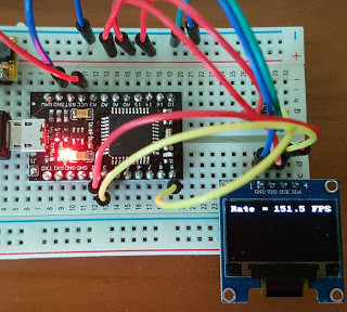
That’s precisely what pushed [Larry Bank] to see how well he could optimize the frame rate on the popular SSD1306 OLED display. After several iterations of his code, he was able to achieve a blistering 151.5 FPS, with apparently still some room for improvement if he’s feeling up to the challenge. But considering his first attempt was only running at 5.5 FPS, we’d say he’s already more than earned his hacker cred on this one.

A few different tricks were used to achieve such incredible performance gains. To start with, while the official I2C specification says you’re supposed to wait for an acknowledgment back from the device when communicating with it, [Larry] realized the SSD1306 didn’t actually care. He could continuously blast commands at the display without bothering to wait for an acknowledgment. He admits there are problems with this method, but you can’t argue with the results.

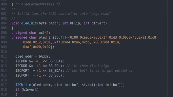
To really wring all the performance out of the system he could, [Larry] donned his Assembly Cap and examined how the Arduino IDE compiler was interpreting his code. He identified a few areas where changing his C code would force the compiler to generate faster output. He notes that this wouldn’t normally be required when working with more advanced compilers, but that the Arduino toolchain needs its hand held occasionally.

This isn’t the first time we’ve seen somebody try and push more pixels through the very same OLED display, and it’s interesting to see the two very different approaches to the same goal.

Windows Notepad Now Supports Unix Line Endings

In what is probably this century’s greatest advancement in technology, Windows Notepad now supports Unix line endings. This is it, people. Where were you when Kennedy was assassinated? Where were you when Neil Armstrong set foot on the moon? Where were you when Challenger blew up? Where are you now?

Previously, Windows Notepad only supported Windows End of Line Characters — a Carriage Return (CR) and Line Feed (LF). Unix text documents use LF for line endings, and Macs use CR for line endings. The end result of this toppling of the Tower of Babel for End of Line characters is a horrific mess; Windows users can’t read Unix text files in Notepad, and everything is just terrible. Opening a Unix text file in Windows produces a solid block of text without any whitespace. Opening a Windows text file in anything else puts little rectangles at the end of each line.

Starting with the current Window 10 Insider build, Notepad now supports Unix line endings, Macintosh line endings, and Windows line endings. Rejoice, the greatest problem in technology has now been solved.

Putting The Mooshimeter To Sleep With A Bit Of Mercury

If you haven’t heard of it, the Mooshimeter is a two channel multimeter that uses your smartphone as a display over Bluetooth 4.0. The ability to simultaneously monitor voltage and current is rather unique, and the fact that you aren’t physically tethered to the thing makes it ideal for use in hard to reach or even dangerous locations. The promotional material for the Mooshimeter shows users doing things like leaving the device inside the engine compartment of a car while they drive around and take readings about the vehicle’s electrical system.

Note the vertical orientation

All that sounds well and good, but at the end of the day, the Mooshimeter is probably not going to be your primary multimeter. It’s going to stay on a shelf until a task befitting its unique abilities comes along. Unfortunately, as [nop head] found, that can be a problem. Like many modern devices, the Mooshimeter doesn’t actually turn off. It just sits there draining its battery until you’re ready to use it. Which of course means that when you’re finally ready to pull the thing out and put it to use, you get a low battery warning and need to put new AAs in it. First World problems.

The fix for this thoroughly modern problem is delightfully old school: a mercury tilt switch.

Using a small spacer made of Kapton tape, [nop head] was able to isolate the battery contacts from the PCB itself. He then soldered the mercury switch in place between them, making sure to position the bulb vertically. When the Mooshimeter is right side up, the mercury flows down and bridges the contacts; but when the device is inverted the contact is broken and the batteries stop draining. He still has to remember to put the Mooshimeter face down when he’s done with it, but it’s better than dealing with constant dead batteries.

There was a lot of initial interest in the Mooshimeter when it was announced in 2014, but we’ve seen precious little of it since. It certainly seems neat, but perhaps it’s a bit too niche for its own good? If Mooshimeter fulfills a critical role in your tool set, let us know in the comments below.

Stomping On Microcontrollers: Arduino Mega Guitar Effects Pedal

Effects pedals: for some an object of overwhelming addiction, but for many, an opportunity to hack. Anyone who plays guitar (or buys presents for someone who does) knows of the infinite choice of pedals available. There are so many pedals because nailing the tone you hear in your head is an addictive quest, an itch that must be scratched. Rising to meet this challenge are a generation of programmable pedals that can tweak effects in clever ways.

With this in mind, [ElectroSmash] are back at it with another open source offering: the pedalSHIELD MEGA. Aimed at musicians and hackers who want to learn more about audio, DSP and programming, this is an open-hardware/open-software shield for the Arduino MEGA which transforms it into an effects pedal.

The hardware consists of an analog input stage which amplifies and filters the incoming signal before passing it to the Arduino, as well as an output stage which does the DAC-ing from the Arduino’s PWM outputs, and some more filtering/amplifying. Two 8-bit PWM outputs are used simultaneously to make pseudo 16-bit resolution — a technique you can read more about in their handy forum guide.

The list of effects currently implemented covers all the basics you’d expect, and provides a good starting point for writing custom effects. Perhaps a library for some of the commonly used config/operations would be useful? Naturally, there are some computational constraints when using an Arduino for DSP, though it’s up to you whether this is a frustrating fact, or an opportunity to write some nicely optimised code.

[ElectroSmash] don’t just do pedals either: here’s their open source guitar amp.

Continue reading “Stomping On Microcontrollers: Arduino Mega Guitar Effects Pedal”

Mike's robot dog

Mike’s Robot Dog Is A First Step In The Right Direction

Humans can traverse pretty much any terrain thanks to their legs and fast-acting balancing system. So if you want a robot which should have equal flexibility, legs are a good way to go, this confirmed by all the achievements of Boston Dynamics’ robots. It was therefore natural for [Mike Rigsby] to model his robot dog after Boston Dynamics’ dog-like robot, SpotMini.

The build log on his Hackaday.io page makes for interesting reading. For example, he started out with the legs oriented like SpotMini but found that when trying to stand, the front legs worked fine but the rear ones slid or the dog shifted rearward or both happened. His solution was to take a cue from his 1990s Sony robot dog, Aibo, by reversing the orientation of the rear legs. He then upgraded his servo motors to ones with double the torque and increased the strength of the legs’ structure. In the first video below, you can see that his dog now lifts itself up to a standing position perfectly.

So far, to give it more of a dog-like personality he’s mounted Google’s AIY Vision Kit which changes a light’s color based on the degree to which a person is smiling, though we think a wagging tail would work well too. The possibilities are endless but one step at a time. See the second video below for a demonstration of the use of the Vision Kit.

Continue reading “Mike’s Robot Dog Is A First Step In The Right Direction”

Sophie Wilson: ARM And How Making Things Simpler Made Them Faster & More Efficient

Sophie Wilson is one of the leading lights of modern CPU design. In the 1980s, she and colleague Steve Furber designed the ARM architecture, a new approach to CPU design that made mobile computing possible. They did this by realizing that you could do more, and quicker, with less. If you’ve use a Raspberry Pi, or any of the myriad of embedded devices that run on ARM chips, you’ve enjoyed the fruits of their labor.

It all began for Sophie Wilson with an electric lighter and a slot machine (or fruit machine, as they are called in the UK) in 1978. An aspiring thief had figured out that if you sparked an electric lighter next to the machine, the resulting wideband electromagnetic pulse could trigger the payout circuit. Electronics designer Hermann Hauser had been tasked with fixing the problem, and he turned to Wilson, a student working at his company.

Wilson quickly figured that if you added a small wideband radio receiver to detect the pulse, you could suppress the false payout, foiling the thief. Impressed with this innovation, Hauser challenged Wilson to build a computer over the summer holidays, based in part on a design for an automated cow feeder that Wilson had created at university. Wilson created this prototype computer that looked more like a hand-wired calculator than a modern computer, but the design became the basis for the Acorn System 1, the first computer that Hauser’s new company Acorn Computers launched in 1979. Continue reading “Sophie Wilson: ARM And How Making Things Simpler Made Them Faster & More Efficient”

We Couldn’t Resist This CNC Batik Bot

Batik is an ancient form of dyeing textiles in which hot wax is applied to a piece of cloth in some design. When the cloth is submerged in a dye bath, the parts covered with wax resist the pigment. After dyeing, the wax is either boiled or scraped away to reveal the design.

[Eugenia Morpurgo] has created a portable, open-source batik bot that rolls along the floor and draws with wax, CNC-style, on a potentially infinite expanse of cloth. The hardware should be familiar: an Arduino Mega and a RAMPS 1.4 board driving NEMA 17 steppers up and down extruded aluminium.

Traditionally, batik wax is applied with a canting, a pen-like object that holds a small amount of hot wax and distributes it through a small opening. The batik bot’s pen combines parts from an electric canting tool with the thermistor, heater block, and heater cartridge from an E3D V6 hot end. [Eugenia] built the Z-axis from scrap and re-used the mechanical endstops from an old plotter. Check out the GitHub for step-by-step instructions with a ton of clear pictures and the project’s site for even more pictures and information. Oh, and don’t resist the chance to see it in action after the break.

We love a good art bot around here, even if the work disappears with the tide.

Continue reading “We Couldn’t Resist This CNC Batik Bot”