Thanks to microcontrollers, RTC modules, and a plethora of cheap and interesting display options, digital clock projects have become pretty easy. Choose to base a clock build around a chip sporting a date code from the late 70s, though, and your build is bound to be more than run-of-the-mill.
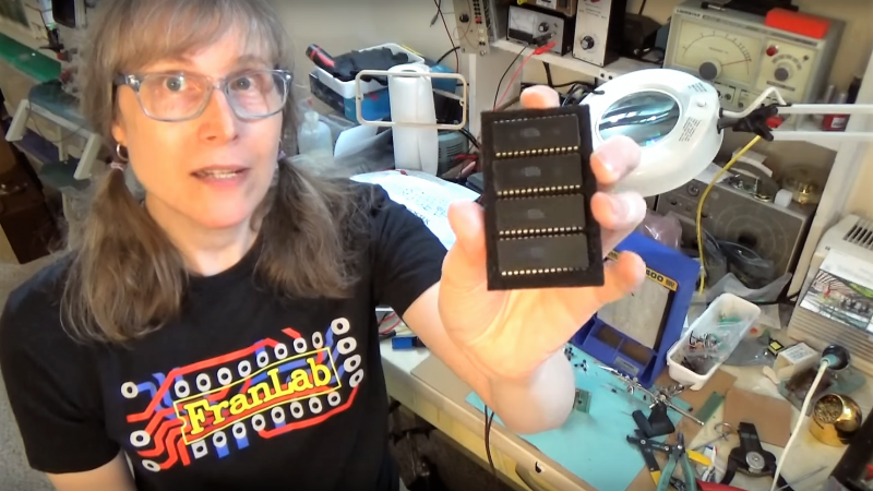
This is the boat that [Fran Blanche] finds herself in with one of her ongoing projects. The chip in question is a Mostek MK50250 digital alarm clock chip, and her first hurdle was find a way to run the clock on 50 Hertz with North American 60-Hertz power. The reason for this is a lesson in the compromises engineers sometimes have to make during the design process, and how that sometimes leads to false assumptions. It seems that the Mostek designers assumed that a 24-hour display would only ever be needed in locales where the line frequency is 50 Hz. [Fran], however, wants military time at 60 Hz, so she came up with a circuit to fool the chip. It uses a 4017 decade counter to divide the 60-Hz signal by 10, and uses the 6-Hz output to turn on a transistor that pulls the 60-Hz output low for one pulse. The result is one dropped pulse out of every six, which gives the Mostek the 50-Hz signal it needs. Sure, the pulse chain is asymmetric, but the chip won’t care, and [Fran] gets the clock she wants. Pretty clever.
[Fran] has been teasing this clock build for a while, and we’re keen to see what it looks like. We hope she’ll be using these outsized not-quite-a-light-pipe LED displays or something similar.


Lotsa folks used 24 hrs before military or continued after. I STILL get cinfused with 12 PM being lunch time, because 1 PM ought to come 11 hours before 12 PM, not 1 hour after. I HATE having to stop and figure it out or set something to 11:59 AM or PM to be SURE it’s right. What’s wrong with 0 or 00 AM ? It’s 0 or 00:01, dear. 12:01 before 1:01?!? Idiocy. It puts irregular rules into math as english has. Thanks, Fran.
AM: ante-meridiem PM:post meruidiem
Literally, before noon and after noon. That noon is 12:00, rather than 00:00, is a historical artifact like so many others. This one comes from a time before minutes and seconds (literally ‘smaller’ and ‘second smaller’, from ‘second minute’), and, in fact, a time before conventional use of zero. Hours were counted from midnight and noon. 12:00PM (PM by convention, due to continuity…. Neither 12 is really AM or PM in a formal way. If 12:01 is PM, then so should be 12:00) is 12 hours past midnight, but also after noon. 1PM is one hour past meridiem.
If you don’t like it, you still need to deal with it. It is funny, though, how many people I have run across that have the same feeling. And how many of them stick to Imperial units (Imperial is the unit names… the particular measures are locale dependent, such as US conventional, British conventional, the former British conventional, and so on…. Bloody annoying to an engineer)
Uh, Imperial? I don’t think that term applies here, even as unit.
The Roman Empire, I’d say that was Imperial.
B^)
12:01 PM should be the same as 00:01 AM.
Title is confusing. The 50hz clock is being tricked to work with 60hz power.
I found the write up confusing. I had to read through it a couple of times to understand what was going on.
I would have thought the easy design choice (and always thought it was) would have been to have this in the IC and have the 50/60Hz select choose between dropping or not dropping a cycle periodically. Instead, the one I just looked up uses two different divider sections, depending on input frequency. Pretty much the same number of gates either way.
Good simple solution. I have a similar issue with the microwave in the RV, but I’ll need a quartz solution.
For either the generator or inverter, the power frequency is unstable and the engineer who picked the microwave used one which still uses the line frequency for the clock. It drifts by up to 20 minutes a day. Future project.
Outstanding!
Very good, imaginative hack, Fran. Engineering skills and expertise pays.
[…and I thought I was the only one who still had MK50250s and MK5017s (my MK5017 clock is a single chip driving six V-F tubes directly; match that these days!)]
…and displays the month and day, as well as the time….
I built a digital clock when I was in college back in the ’70s that used the 60 Hz line frequency as its counting mechanism. It worked, but the wiring was a mess and I knew nothing about bypass caps and noise prevention. At the time, though, it was an almost trivial matter for a chip designer to convert the 60 Hz line frequency into a 60 second minute. Years later I moved overseas to a country that used 50 Hz and all my 60 Hz clock-based appliances, including microwaves and VCRs, wouldn’t work properly. To use Fran’s method I would have to add a pulse, rather than take one away to get the clock circuits to work properly. How could that be accomplished without resorting to a quartz crystal and one or more frequency divider chips?
To do that, look up ‘phase locked loop’. You make an oscillator circuit that syncs a free running 60Hz oscillator to the 50Hz power line.
A PLL can be tricky to get working properly – the 4046 can be a right pain. I think I’d go for a pulse doubler every fifth pulse to get 10 more or pulse a doubler every cycle and mask 40 of them out. Once the pulse doubling has been sorted, the rest is simple logic – or do it all in an eight pin processor keeping the line frequency as the reference.
Some interesting thoughts, thank you. Using a PIC or similar uC is the smart, modern way to go, but this might make an interesting first-time project for a small FPGA instead. I’m just now reading up on the things – could be a fun project.
I occurred to me after posting, the first part could be achieved by using the full wave rectified supply before the filter caps. (add another series diode before the caps). This gives the 100Hz. reference. Now you just need some logic to remove 4 out of 10 pulses. Perhaps a 4017 divide by 10 and ‘diode or’ four of the outputs to pull the clock line high.. Or some gates if you want to do the job ‘properly’. And I think you’re there.
I think you’ll find that the likes of a Mostek MK50250
won’tcan’t be duplicated bys a small FPGA. If you really want a clock, either buy a ’70s/’80s-era clock chip or use a TRUE microcontroller.Want to really start to learn electronic design at the ‘fran’ level? DESIGN and build a clock using logic ICs (CMOS; TTL); it’s as easy as programming a computer chip and a lot more satisfying since you’re actually learning something useful.
I think that this is a good candidate for a small 5v cpld.
It is still on my todo list to buy a stack of the 9500XL series so that I can one day build something out of all of my old silicon.
Many of those 60Hz clocks would save on LED’s and have the first digit only be one or blank no zero or two. I have to pry open the plastic covering the big display only to find the diodes aren’t there. Even if the chip has a pin for 12/24 the clock is hard to convert.
The they in the first post are the Romans. They had no zero in their math. Sunrise and set were at 6AM and 6PM year round! Roman-Imperial is a better term for what the US is stuck with.
There is no legal defined time of 12:00 being either A or P only the words noon and midnight stand up in a court of law.
Times in Rome involved divided the day and night into twelve equal segments, but the length of those segments varied with the season.
Time counted from sunrise to sunset and then to the following sunrise. Rome is about 42°N, so the days ranged from roughly 9 hours long to roughly 15. So, yes, at the summer solstice an hour of the day was almost twice as long as an hour of the night.
https://en.wikipedia.org/wiki/Roman_timekeeping
I was going to say that most of the early vlsi had provisions for 50 or 60hz. I would start by looking up the chip and seeing if there is not a pin to control that before messing around with more hardware.
… and then you actually watched the video where Fran showed us that MOSTEK made three different ICs, one always displayed 12-hour time, one always displayed 24-hour time, and the most common one coupled the prescaler to the display?
Right? :P
What an ingenious hack!
I too would not immediately have thought of it.
With timing signals you just naturally tend to think they have to be in equal segments.
This technique is properly called “pulse swallower”. Used is various frequency synthesizers since the 60’s or 70’s (I think). Interesting to see it applied for 60->50 Hz.
Very serious question for all you master hackers, AND hackers-in-training–
Why aren’t you using that seriously powerful hacker’s computer tool, the Raspberry Pi 3B+, to build a seriously powerful, do-everything clock?
Forget the ‘do-everything’ clock…most hackers just want to build a working, serviceable clock. So why not a simple clock, for training purposes? After all that’s what the RPi is for, and about: training and ease of use.
I find the lack of the RPi as a basis for one of the staple hackers’ projects–the clock–really baffling.
It’s well known the Pi is not powerful enough to calculate the next value to display on the clock before the new value is due. The preferred way to handle the task would be a networked cluster of Pi’s, each driving a single LED segment of the clock display, all of them controlled through a secure VPN by a powerful server in the cloud commanding each Pi to turn its LED on or off as needed, with a LAMP stack to run the webpage you can use to set the clock and a RESTful API for further integration. All neatly packaged into a Docker container, with a DevOps team on 24/7 standby for any issues that will – not if but when – arise, so your morning wake-up alarm won’t be thwarted by the occasional evil DDOS attack. See? Easy!
Boys! Don’t make me come down there!
B^)
Is that a
“Boys, don’t make me come down there and try to design a Raspberry-Pi-based clock!”
?
“It’s well known the Pi is not powerful enough…”
I’m torn between your wonderful use of humor, and the simple, unavoidable fact that examples of the use of a Raspberry Pi as a basis for a simple digital clock are not only not prevalent–they are non-existent.
The Raspberry Pi was envisioned as, and has enjoyed unparalleled success in teaching the basics–and beyond–of programming and computers to countless children, as well as young–and not-so-young–adults.
A digital clock is probably one of THE most prevalent, ubiquitous, fairly sophisticated electronic devices extant. It also, at the same time, enjoys the charming attribute of having a simple design which is understandable by, and capable of being implemented by any and all of those people to which the Raspberry Pi group promotes this product.
“…It’s well known the Pi is not powerful enough…. 1.4 GHz processor? Forty Input-Output pins? One megabyte of RAM? Gigabytes of SD-card storage? And the best attention-grabber and ‘easily-relatable’ hardware example anyone can give to a new Raspberry Pi user is the flashing of an LED?
We’re insulting our children.
Edit—
Make that “One GIGABYTE of RAM…” And make that
“…We’re insulting our children as well as NOT doing anything to make computers and electronics more exciting by not showing them just exactly how these topics are meaningful and immediately relevant to their everyday lives.”
Perhaps the combination of technology, and relating to children, is far too important a task…
So looking at 50 Hz and 60 Hz, you would have a common multiple at 300 Hz so you need a circuit that multiplies the 60Hz by 5 to get 300 Hz and then a divide by 6 circuit to get down to 50 Hz, You could go the other way by multiply by 6 and divide by 5, that’s all there is to it.