
Parallelism is your friend when working with FPGAs. In fact, it’s often the biggest benefit of choosing an FPGA. The dragons hiding in programmable logic usually involve timing — chaining together numerous logic gates certainly affects clock timing. Earlier, I looked at how to split up logic to take better advantage of parallelism inside an FPGA. Now I’m going to walk through a practical example by modeling some functions. Using Verilog with some fake delays we can show how it all works. You should follow along with a Verilog simulator, I’m using EDAPlayground which runs in your browser. The code for this entire article is been pre-loaded into the simulator.
If you’re used to C syntax, chances are good you’ll be able to read simple Verilog. If you already use Verilog mostly for synthesis, you may not be familiar with using it to model delays. That’s important here because the delay through gates is what motivates us to break up a lot of gates into a pipeline to start with. You use delays in test benches, but in that context they mostly just cause the simulator to pause a bit before introducing more stimulus. So it makes sense to start with a bit of background on delays.
Delays in Verilog
For our purposes, delay in Verilog is pretty simple. The simulator uses a unitless time interval that you can set using the `timescale directive. The reality is, that timescale really doesn’t do anything special but label what that lowest-level tick is. I used 1ns/1ps as a timescale which makes each tick worth 1ns with the measurements in picoseconds. However, it really doesn’t matter in this case as long as you think of ticks.
There are several different kinds of delays and several ways Verilog can model them. For what we want, we only need a very simple delay from the output of some piece of code until it is sent somewhere else. You often hear about inertial delay and transport delay. A wire or gate with an inertial delay will lose any input that doesn’t at least meet the delay time. So a gate with a delay of 5 (you’ll see how to specify that shortly) would miss a pulse of width 2, for example. With a transport delay, the entire signal is simply shifted in time no matter what. So the pulse of width 2 would still appear in the output, just 5 time units later.
For our examples, we don’t care much. We just want to make some combinatorial logic take “a long time” so we’ll keep it simple. If you want to read a lot more about delays in Verilog and why most people are doing them wrong, there’s a great paper about that (PDF).
All that’s great, but we are just going to introduce some delays in some logic functions using assign like this:
assign #5 x=y;
In this case, when y changes, x won’t actually change for 5 ticks, whatever a tick is. This is known as an inertial delay. Technically, any change to y that doesn’t last at least 5 ticks will be lost because this is an intertial delay, but for now that’s fine.
There’s a lot more to delays. You can have a minimum, typical, and maximum delay. You can also specify up to three types of delays for rise time, fall time, and turn off time. We don’t care about that much detail, but it is good to know it is there.
Here’s a good short video about the relationship of timescales to delays:
Some Integer Math
Here are some small functions that, when combined, will compute (4x+3)/2 using integer math:
module f1(output [15:0] f, input [15:0] x);
assign f=x<<2;
endmodule

module f2(output [15:0] f, input [15:0] x);
assign f=x+3;
endmodule

module f3(output [15:0] f, input [15:0] x);
assign f=x>>1;
endmodule
I broke these out so they could each be given a delay elsewhere. You can open and try the whole project, by the way, on EDAPlayground.
You can add all of these together into one big lump of gates:
module flatmain(input clk, output [15:0] f, input [15:0] x);
assign #`compdelay f=int3;
wire [15:0] int1;
wire [15:0] int2;
wire [15:0] int3;
f1 u1(int1, x);
f2 u2(int2, int1);
f3 u3(int3,int2);
endmodule
This is the Verilog equivalent of taking three ICs and wiring them together. There’s no clocking going on here. The only delay is from the delay statements.
The compdelay variable is 6 because each of the “f” functions takes 1 clock (two ticks). Why? Because that’s what I wanted for the demo. In real life, those functions would take almost no time to compute. More complex structures do take significant time and here I wanted the delays to stand in for those more complex operations to keep the code example simple.
Illustrating the Problem
The testbench cycles the input as follows: 0, 1, 0x64, 2, 3, 4. The expected result is 1, 3, 0xc9, 5, 7, and 9. The way everything is set now, that works great:
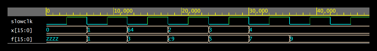
Notice, however, that the clk signal is generated every 6 ticks, so the total delay should be 6 ticks, or 1 clock cycles. The diagram shows that’s correct. The input holds for 1 clocks and the output appears 1 clock later. I made the testbench to go as fast as possible. If you like, change the slowclock parameter from 3 to 2 in config.v (that will cause the clock to take 4 ticks instead of 6). The result won’t be good:
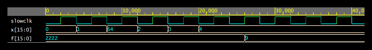
In real life, it might be worse because the delay model isn’t necessarily how a real circuit will behave. Regardless, the answer isn’t going to be correct. So increasing the clock speed is not possible with this configuration.
Pipeline to the Rescue
Have a look at this alternate main function:
// pipeline
// x->ff0->(f1)->int1->ff1->(f2)->int2->ff2->(f3)->f
module main(input clk, output [15:0] f, input [15:0] x);
wire [15:0] int1;
wire [15:0] int2;
reg [15:0] ff0, ff1, ff2;

f1 #2 u1(int1,ff0);
f2 #2 u2(int2,ff1);
f3 #2 u3(f,ff2);

always @(posedge clk) ff0<=x;
always @(posedge clk) ff1<=int1;
always @(posedge clk) ff2<=int2;

endmodule
I’m still using the same functions, but I’ve put a flip flop at the front and after u1 and u2. Well, technically 16 flip flops, one for each bit, but you know what I mean. That’s all it takes to pipeline this design. I coded the two tick (one clock cycle) delays for each element here, as well.
Look at the same test sequence:
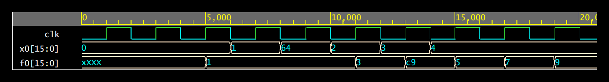
This time, I still send a new value every clock cycle, but the clock cycles are the same as one tick in the previous waveforms. It looks like two ticks, but note the scale. The first major mark on the axis is 5,000 ps but in the previous waves that same distance was 10,000 ps.
After the initial latency, I get a result every clock cycle, too. Note that the total time is now 18 ns compared to 35 ns, before. However, the initial output of 3 is later due to the pipeline latency. So a faster clock and a better throughput. Well worth the slight increase in complexity.
End of the Pipe
As I mentioned in the previous post, there are many schemes you might try to make the pipeline more robust including adding FIFO buffers or using handshaking between the different elements. However, the principle stays the same. By handing off smaller chunks of work between circuits working in parallel, you can take better advantage of FPGA resources and increase speeds dramatically.


I think there is a small error.
Either the formula you want to compute is wrong or module f2.
Fromula:
(4x-3)/2
f2:
module f2(output [15:0] f, input [15:0] x);
assign f=x+3;
endmodule
Did you mix up the signs?
Yeah. Will fix. I had a few examples that flipped in and out that I changed for one reason or another. Good catch.
Great!
Nice article anyways!
I have one remark. At our university it was good practice to sample all in and outputs of each module and try to increase the module size as much as possible.
Big module sizes are good for increasing parallelsism (so to speak keep much of the FPGA busy).
Sampling is needed, because in reallife input data will change not only during clock transitions but also in between. If the data changes during one clock cycles and you hae unsampled inputs, you risk glitches in your outputs.
Absolutely. These are small as examples and have unrealistically large delays. But I didn’t want to distract from the core concept.
Yeah I agree! Keeps the transistion from software programming to hardware description softer :)! Once you got it you can then start fighting with timing :D !
The FPGA version of a spherical cow.
You might also want to do a double take on the first example where you wire it all up (in particular the number of times you’re assigning to wire ‘f’ and just what value ‘int3’ is ;-)
f is local but if you click on the EDA Playground link, the int3 is a typo (fixed in a sec).
The whole “timescale” thing is something that has always bugged me about Verilog — that and using blocking vs. non-blocking assignments.
I learned VHDL first. There IS no such thing as a “timescale.” If you want a #1 delay, you delay for 1ns. Or you can delay for 3fs (femto-seconds). There is no artificial limit on your timing resolution. Yes, your sims may run a tiny bit slower, but you never have timing issues.
Also, in VHDL, all hardware is non-blocking. You only use blocking statements in testbenches. I greatly prefer this.
But, to be fair, VHDL is also more verbose, and Verilog known how to do math without having to load libraries. Other than those two annoyances, I greatly prefer Verilog.
You mean you prefer VHDL?
No. I like Verilog better. It has a couple of annoyances, but it is easier.
VHDL is natively stupid. You can’t even do “signal = signal + 1” without including a library that tells it how to do math. This bring flexibility in that you can create your own types of number encoding, but the vast majority of people will never have to do that (I know that I never did), so it is just extra hassle for most people.
VHDL also requires separate entity and architectures in separate files. This is pretty much identical to “C” having separate .c and .h files. So if you add a signal to your module, you have to remember to add it in two places. This is rather a pain to have to keep track of while your design is in a state of flux.
Also, if a signal is an output type, then it is output ONLY. You cannot read it back into your block under any circumstances. So the following pseudocode is illegal:
output clock
after 10ns clock = not clock
This code will FAIL because you are trying to read (use) an output signal. Yes, this is stupid. To get around this, you have to code like this:
output clock
signal internal_clock
after 10ns internal_clock = not internal_clock
clock = internal_clock
Yes, twice as many lines.
Timescale and delay are simulation concepts only and will not synthesizeian. You’ve gotten good at pipelining simulation in verilog, not pipelining in FPGAs. Sorry.
*synthesize
Well of course but I’m trying to show how it works through simulation. The functions stand in for real logic that had actual delays. I thought that was evident from the text.
Apparently I’m that hackaday commenter today. Sorry, I shot to the comments too early.
It doesn’t seem to be a great example. If you drive the flatmain dut with x0 it will produce outputs just as fast as the pipelined version. The f1-f3 modules have transport delays and are effectively pipelining it without needing the registers.