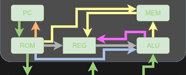
Parallelism is your friend when working with FPGAs. In fact, it’s often the biggest benefit of choosing an FPGA. The dragons hiding in programmable logic usually involve timing — chaining together numerous logic gates certainly affects clock timing. Earlier, I looked at how to split up logic to take better advantage of parallelism inside an FPGA. Now I’m going to walk through a practical example by modeling some functions. Using Verilog with some fake delays we can show how it all works. You should follow along with a Verilog simulator, I’m using EDAPlayground which runs in your browser. The code for this entire article is been pre-loaded into the simulator.
If you’re used to C syntax, chances are good you’ll be able to read simple Verilog. If you already use Verilog mostly for synthesis, you may not be familiar with using it to model delays. That’s important here because the delay through gates is what motivates us to break up a lot of gates into a pipeline to start with. You use delays in test benches, but in that context they mostly just cause the simulator to pause a bit before introducing more stimulus. So it makes sense to start with a bit of background on delays.
Continue reading “Getting Good At FPGAs: Real World Pipelining”


