Do you need a bias tee? If you want to put a DC voltage on top of an RF signal, chances are that you do. But what exactly are bias tees, and how do they work?
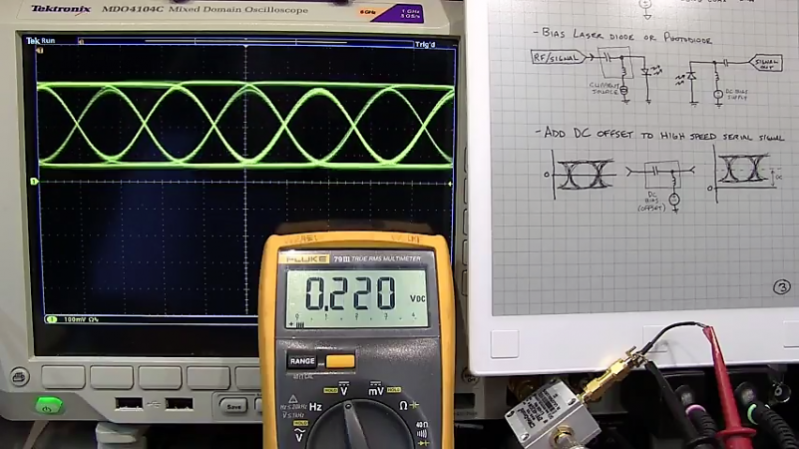
If that’s your question, [W2AEW] has an answer for you with this informative video on the basics of bias tees. A bias tee allows a DC bias to be laid over an RF signal, and while that sounds like a simple job, theory and practice often deviate in the RF world. The simplest bias tee would have a capacitor in series with the RF input and output to pass AC but block DC from getting out the input, and a DC input with a series inductance to prevent RF from getting into the DC circuit. Practical circuits are slightly more complicated, and [W2AEW] covers all you need to know about how real-world bias tees are engineered. He also gives some use cases for bias tees, from sending DC signals up a feed line to control an antenna tuner or rotator to adding a DC bias to a high-speed serial line.
It’s an interesting circuit, and we learned a lot, which is par for the course with [W2AEW]’s videos. Check out some of his other offerings, like a practical guide to the mysteries of Smith charts, or his visualization of how standing waves work.


Oh why does everything have to be by video these days? I much prefer to scroll through a written article with diagrams at my own pace and picking out the bits that are relevant to me and my knowledge/expertise level. I just don’t have the time in my life to sit watching videos, and it is v.difficult to bookmark an interesting bit half way through a video. And don’t get me started on video ads…
Totally agree. Video is great for some aspects or showing a particular bit. It’s sort of like where we were a few years ago with death by power point now its death by video.
I have to say I whole-heartedly agree with this. Nevermind the time, the quick-browse-ability, *search-ability*, nevermind the lack of usability as a reference–can’t friggin’ print the page and add your own notes, and a million other factors, if none of that’s enough, just think about the friggin’ data usage!
Not a comment on this particular resource, nor a comment that things like this *shouldn’t* be in as many forms as it takes to inform folk of various learning-styles, but a comment on the increasing trend–that seems to have no plateau–which seems to be impeding the creation, quality, disbursement, value-for, and more, of resources in other forms.
“video killed the radio star” and a gazillion other things…
So, does a HaD writer get paid the same for a short article with an attached video, compared to a lengthy written article? And is there a bonus for either if generates a lot of comments?
B^)
The problem isn’t video in general, it’s people who make low quality video.
In this case, the narrator is reading text visible on the screen, which is a known awful technique. (Hint: never do that!). The video should be used to enhance and augment the information: it’s much better to have dialog over text that *isn’t* read aloud by the narrator, or even better is to have no text at all and show *examples* of what the narrator is talking about.
And even that is non-optimal, since showing examples could be done in a static picture. To make best use of video he should manipulate and *show* the workings of examples using the video, while narrating the list. (Also, people don’t find lists particularly useful or informative.)
He has good vocal variety and delivery, no (or few) disfluencies, so his voice is an asset: it won’t put you to sleep.
It’s unfortunate – I had never heard of bias tees, was excited to learn something new, and the video is only pages of bullet points.
(How is the low frequency limit derived? Where did that formula come from? Is that something standard?)
Every time I tried to read what he was showing on the paper, he blocked the text by waving his pencil over it. In some cases, not this one apparently, it’s a matter of, Genius + illiterate = Video.
Totally agree. JR
Bias “T”s (phantom power feeds) aren’t limited to RF. They can be quite useful for digital signals going to remote sensors.
You can get quite significant data rates (with power feed) over unbalanced (coaxial) cable.
You can even make the data link bi-directional over the one wire.
Has anyone powered a ESP with a cheap bias tee ?
Do you mean powering it from the DC port on a bias T? You could definitely do that. If the coax you already have is AC, then you need two bias Ts, one at the beginning of the run and one at the end. I haven’t powered an ESP but I’ve powered things like LNAs using them over long coax runs.
Transmitter –> (RF) Bias T (RF+DC) –> Coax –> (RF+DC) Bias T (RF) –> Receiver
And hook a power supply up to the DC port on the first bias T and your ESP power pins to the DC port on the second.
Yes, exactly that. Now how to correctly design the components and PCB to do that in reality ?
I like the first inductor to be something like TAIYO HK1608-18NKT (300mA max) for the 2.4GHz LNAs we used at work, but a VNA is handy to confirm your specific setup’s signal losses. Note, those U.FL connectors on boards are only rated for something like 20-50 uses, but the 50ohm cables are cheap.
Well it depends what you want to do?
You want to combine the DC power supply for an ESP8266 *with what* in a single cable?
Choosing the bias tee components depends… what is the transmission line impedance? What is the frequency domain of the desired AC component?
Transmission line is ~20 meters of 50Ω RG316 ~2.4GHz (WiFi signal). The idea is to power and control in a secure way (no WiFi interference) a big array of cheap sensors / actuators. DC power should be up to 24V 1A.
jcamdr – you explicitly did not answer the important half of the question, the part about what the AC bandwidth would be. What is your comm signal – you’re not going to use uart-type serial as that will have a DC component. Are you planning on using some kind of RF? What modulation? What bandwidth? And so on. Once you know those things, designing a Tee is trivial. And it goes back and forth – if you need LF content in your signal band, you need a larger inductor (higher cost, and self resonance limits the HF limit lower). So you might design your signal to fit a Tee design that’s cheap/easy to make for example, or at least balance one vs the other.
Thanks for your message and sorry if I was not clean enough. The RF bandwidth is the one of the 2.4GHz WiFi signal that the ESP8266 is able to handle. According to the datasheet:
Protocols 802.11 b/g/n
Frequency Range 2.4G ~ 2.5G (2400M ~ 2483.5M)
Tx Power
802.11 b: +20 dBm
802.11 g: +17 dBm
802.11 n: +14 dBm
Rx Sensitivity
802.11 b: –91 dbm (11 Mbps)
802.11 g: –75 dbm (54 Mbps)
802.11 n: –72 dbm (MCS7)
I knew a guy trying to catch the eye of a girl who was into musicians. He wanted her to think he was a gifted musician but didn’t want to be bothered learning an instrument. So he just practiced a single piano composition (Schumann’s Toccata I think) over and over until he could play it convincingly. When she saw him play, she said “Eww, No. Play Tiny Dancer.”
All the RF stuff on Hackaday and most HAMs remind me of that story.
Some of us hams have more depth than that. We can play “Tiny Dancer.” But most of the ones who can are pros. Not everybody can be an RF engineer. There is a place for amateurs in this game.
It’s just the mindset I find similar.
What’s the epaper taböet he has?
https://remarkable.com/, I think.
Great, this article may come just in time to help me understanding something: how it is possible to send AC (not DC) power supply in addition to RF in a single coax cable?
It seems this is what is done for remotely powering amplifiers over coax for cable Docsis+Digital TV distribution networks, with power voltage between 40 to 90 VAC (most common seems to be around 60).
Exemple of equipments:
– UPS: http://broadband.alpha.com/products/item/xm3-hp-series
– Service Power Interface: http://www.alphatechnologies.com/download/554_service_bypass_datenblatt.pdf
– Power Inserter: https://www.teleste.no/3lpi-sa-1-2ghz-power-inserter-15a-utendorsbruk
– Remotely powered amplifier: http://www.comtech.co.hu/media/k2/attachments/PG-2018-01-LE1200-EN.pdf
Also, i guess that if ones want to use any kind of measurment device like a digital TV spectrum analyzer or Docsis network analyzer, it should NOT be connected directly to a coax cable carrying such an AC voltage? Except of course if this device is known to have been designed to support such voltage.
The remotely powered amplifier’s block diagram sort of shows how it works. Basically it’s just a diplexer – common port comes in carrying the two signals, and it has a low-pass port and a high pass port (it’s the bit with the LC circuit in a box in the block diagram). Basically it’s just a pair of filters to separate the signals from each other.
There’s no problem sending multiple signals up a cable as long as there’s enough space between them to effectively filter them out. In the satellite world, we do it all the time, usually a lot of things from modems have a 10MHz reference signal and a 1-2GHz (typically military) or 950-1950MHz (commercial) band where the modulated data is (usually only taking up a very small part of that but it can be anywhere in the band. It’s then fed into a ‘block upconverter’ that converts that 1-2GHz signal to where you want it, like 30-31GHz for military Ka-band).
Not sure what cable people do, for satcom you’d usually use a coupler and a load if you want to measure the signal out of, say, a high-power amplifier on a spectrum analyser. The coupler taps off a smaller part of the signal (say, 30dB less than the main path’s power but you can get all different values from 3dB up), and you feed that small signal into the analyser and dump the main signal into basically a heat-sink. Or you can have a coupler as part of a feed network so you tap off any measure a signal and the main path goes to the antenna and is transmitted etc.