In 1976, Texas Instruments came out with the TL084, a four JFET op-amp IC each with similar circuitry to Fairchild’s very popular single op-amp 741. But even though the 741 has been covered in detailed, when [Ken Shirriff] focused his microscope on a TL084, he found some very interesting things.
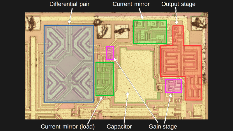
To avoid using acid to get at the die, he instead found a ceramic packaged TL084 and pried off the cover. The first things he saw were four stabilizing capacitors, by far the largest structures on the die and visible to the naked eye.
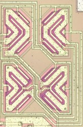
When he peered into his microscope he next saw butterfly shapes which turned out to be pairs of input JFETs. The wide strips are the gates and the narrower strip surrounded by each gate is the source. The drain is the narrow strip surrounding each gate. Why arrange four JFETs like this? It’s possible to have temperature gradients in the IC, one side being hotter than the other. These gradients can affect the JFET’s characteristics, unbalancing the inputs. Look closely at the way the JFETs are connected and you’ll see that the top-left one is connected to the bottom-right one, and similarly for the other two. This diagonal cross-connecting cancels out any negative effects.
[Ken’s] analysis in his article doesn’t stop there though. Not only does he talk more about these JFETs but he goes over the rest of the die too. It’s well worth the read, as is his write-up about the 741 which we’ve also covered.


Fun part of electronic where layout is as important as design.
Like in most of the PCBs when they shall be more than a demo board. E.g. when you have to test your design for EMC compliance or use higher frequencies in itself.
Well, a tlo84 and a 741 are both opamps that follow the same rules of physics, but past that…not that similar (look at slew rate, the reasons for the difference, and the fab process). This article explains about thermal gradients and how to deal with those. Gradients were also intially an argument against putting the pass transistor on the same chip as regulator circuitry – if it hadn’t been worked around, no 7805 etc would exist.
http://www.ti.com/lit/an/snoa737/snoa737.pdf
As a side issue – bipolar opamps make great accidental AM detectors when there’s RFI, jfet opamps don’t.
Maybe the point was that the TI jfet opamps were intended to be general purpose like the 741. There were improved specs, but they weren’t far better than the 741, and their entry price was reasonable. Decades later, there are much better opamps, but the TI series is till valid. The 741 probably should have disappeared, but it’s still good enough for a lot of use.
I once saw a project in the seventies that used a 709 opamp, but without power. The input was used as a clipper, the author deciding he’d get a better match of diodes from an IC opamp.
Michael
Interesting thought. Also interesting is that, if I remember my history correctly (sometimes in doubt) it wasn’t TI who originated this at all – it was National Semiconductor who wrote that app note, and introduced the LF35x and then the lf347 (which is identical to the tlo84 in most regards…). The 351 wasn’t internally compensated for gain = 1 and was very much faster as a result.
TI now owns a bunch of companies that were separate entities back when I did most of my hardware design – at the time, TI was mostly known for TTL, and just coming on the horizon with some decent DSP CPUs.
National Semiconductor app notes are a treasure.
This article is slightly confusing because of the photos chosen. There might be 4 large caps on the *entire* die, but showing only a single of the four op amps on the die leads one to initially believe that the 4 input transistors are what’s being referred to. As usual, skip the Hackaday write-up and go straight to the original article.
… especially Shirriff’s interactive diagram.