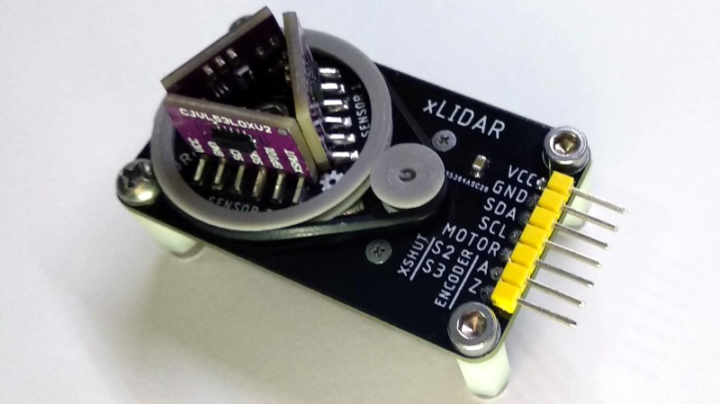
[JRodrigo]’s xLIDAR project is one of those ideas that seemed so attractively workable that it went directly to a PCB prototype without doing much stopping along the way. The concept was to mount a trio of outward-facing VL53L0X distance sensors to a small PCB disk, and then turn that disk with a motor and belt while taking readings. As the sensors turn, their distance readings can be used to paint a picture of the immediate surroundings (at least within about 1 meter, which is the maximum range of the VL53L0X.)
The hardware is made to be accessible and has a strong element of “what you see is what you get.” The distance sensors are on small breakout boards, and the board turns the sensor disk via a DC motor and 3D printed belt drive. Even the method of encoding the disk’s movement and zero position has the same WYSIWYG straightforwardness: a spring contact and an interrupted bare copper trace on the bottom of the sensor disk acts as a physical switch. In fact, exposed copper traces in concentric circular patterns and spring pins taken from an SD card socket are what provide power and communications as the disk turns.
The prototype looks good and sounds like it should work, but how well does it hold up? We’ll find out once [JRodrigo] does some testing. Until then, the board designs are available on the project’s GitHub repository if anyone wants to take a shot at their own approach without starting from scratch.


I love the concept, joined the project.
How fast do you think you can do a 360 scan?
Based on the datasheet it depends which operating mode you are in.
The speed of acquisition affects the maximum range but off the top of my head (read this 2 days ago) in normal mode, one read takes approx 90ms.. then a 360 scan is dependent upon the number of steps, speed of the stepper etc..
I have used a lot of the VL6180X sensors recently, from the same family. There is different settings that could improve the measuring time. The best I have get is about 12ms on a white reflector into complete dark environment for a distance from 10mm to a bit more than 160mm, with a repeatability of about +/-2mm. After calibration and filtering you can hope to get 1mm precision at lower speed.
With a VL53L0X on a open environment and others light source, there will certainly need many measures of the same point to get any usable precision. This will be a very very slow LIDAR.
Passing I2C over a slip ring is usually not a problem as long as you don’t have any electrostatic discharge. This sensors have a unique ID and a writable I2C address, allowing to set each of then with a different I2C address. So If you know where are physically each sensors from there unique ID you can manage them from a single I2C bus.
I looked at using these sensors for something like this a while back, but abandoned the idea when I saw how wide the spread on the sensor was. (more like a flashlight than a laser) Still, I would be interested in seeing how the scans compare to test scenes, especially with some software trickery to try and get a better picture (perhaps paying close attention to the rise/fall of distance measurements relative to position as it rotates to get something more related to a narrow cone in front of the sensor?)
Check out the VL53L1X sensors. They have an adjustable FoV.
No video? What the point then.
The point is that this project is in the very early stages, it takes a lot to this point. I am sure videos will be coming further down the road. I am thankful to be informed of this project and join it at an early stage.
we are hackers, it shouldn’t take polish and completeness to get us excited about something.
the core of the idea is solid. and that makes me interested.
This could be made simpler and (likely) cheaper with a sensor pointing down into a rotating mirror. Cool concept and execution, though. I’ll be following/liking when I get to my PC.
But then you get more cross talk, spherical aberration and other phenomena so it’s easier for accuracy to do it this way.
How exactly do you get spherical aberration from a first-surface mirror?
Because off the shelf mirrors aren’t ‘perfect’.
Mirrors from old HDD platters are near perfect.
Mirrors out of old fladbed scanners are near perfect.
Laserprinters are another hacker’s source of quality mirrors.
Laserprintes also have a (6 to 12) faceted rotating mirror which might be excellent for this application.
Small first-surface mirrors are … affordable. (CO2 lasers and such).
Also, the VL53L0x only needs a very small mirror. Sawing off the axle of a small stepper motor under 45 degree and polishing it probably works, but glueing on a small piece of polished stainless steel or aluminimum is probably easier to do.
Sending data through a makeshift slip ring is neither easy nor accurate. Can you explain this cross-talk and spherical aberration? One, it’s a single-point sample so even if you needed to use a curved mirror, distortion shouldn’t matter. Besides, if you’re spinning the mirror it can be flat.
I’d bet that slip ring using pcb traces and sd card reader springs is going to be incredibly noisy and will require serious debounce and cleaning up in software. But we’ll see.
They are i2c sensors, so noise is not an issue.
I’d still be tempted to add a little conducive lubricant.
I’ve played with inductive power and data transfer before now. If it were one sensor I’d be tempted to make a circular light pipe and add an IR link for the data. Sort of like an optocouper but able to rotate 360 degrees.
If you are concerned with noise through the slip ring you could always use a differential pair.
About 3/4 of the way through the datasheet of the sensor (see st.com) it gives you a very good explanation of the cross-talk so I won’t go into detail here :)
Also regarding mirrors see my reply above.
Does a differential pair help mitigate spikes caused by intermittent disconnects through the brushes? I was thinking about that moreso than EMI.
The datasheet says those sensors have pretty sophisticated countermeasures against cross-talk specifically for a piece of glass or mirror between the sensor and the subject.
And an imperfect or even fully curved mirror still wouldn’t be of concern for a point sample. it’s not capturing a 2d image. The angle of the glass at that point is the angle, the rest of the mirror can be ignored–or am I missing something important here?
Any easy solution would to stick with wires and sweep the sensors back and forth through a 120 degree arc to avoid twisting those wires.
That’s a really good point, thanks.
Wouldn’t be as fast though. Any sort of speed and it’d start shaking itself to bits, the wires would probably be the first bits to come off.
My idea also. The “normal” wire is not really usable forlongevety and you need to use very thin multi stranded wires and make sure it is not bent sharply. Bending the wire 3 to 8 times around the axle in a spiral form (with some guides on the side) would be excellent.
Xiaomi uses very interesting way to transmit data – LED and light senson placed on axis of rotation.
It could be small stm32 or avr on rotating platform gathering data via i2c and serialize it to LED. MCU even can make some filtering.
IIRC you can set windows on the ST ToF sensors for near fixed objects such as glass covers. A mirror should be no different, especially if it’s aimed off-angle.
Why does it need 3 sensors? Are they at different angles, or could you do just as well with one?
It would be interesting to see if the range of these could be increased with some optics on the front. I successfully coupled the previous version of this sensor to some optic fibres, but the sensor still “times out” if you have more than ~100mm of fibre.
Could this make a scanner for 3D printing. Rotate an object inside the viewing field of 3 sensors. Move the z axis up and down with a ball screw. Would the software create a good scan? How can we get it to obj or stl format?
https://www.youtube.com/watch?v=-qeD2__yK4c
This is top class work.
Check out mirror drum and screw geometries…http://www.nbtv.wyenet.co.uk/equipment.htm
Some thoughts: You could angle the sensors at different elevations to provide some ability to detect height. Also you could send the signals wirelessly so that the slip rings are only required to supply power. This could be done using an IR LED and detector facing downwards/upwards on the axis. Alternatively you could use an ESP8266 module using wifi or a small Bluetooth module or some other wireless module. They are cheap and small enough to make that viable.
I like this idea. Make it more radical. This sensor’s Field Of View (FOV) is 25 degrees. Mount one at 0 one +25 other -25 then you will get an up and down FOV of 100 degrees. Would be interesting. I have played with these chips they are great chips.
I realized I did this too fast and HAD doesn’t let you edit. So if you want the greatest FOV then mount them +- 37.5 to give you a total FOV of 75 degrees.
As you would end up with a spiral scan, it should be possible to interpolate to get a higher level of vertical resolution, depending on the sensor speed.
(1) IR link, or
(2) rotary transformer (like those VCRs from 30 years ago)
I did taht too fast and had doesn’t let you.
Any chance of this or something similar will be in production form anytime soon?