The geared DC motor has become the bread-and-butter of the modern-day beginner project. Unfortunately, with the advent of vast online catalogs peddling a wide assortment of these mechanical marvels, validating the claim that one DC motor will outperform the others is a challenge.
Such is the dilemma that our own [Gerrit Coetzee] faced as he set out to buy these geared motors in bulk. In his initial teardown, he quickly compares the change in design, from the original which possess the two-part clutch that extends on overloading, to the clones with the feature disabled altogether.
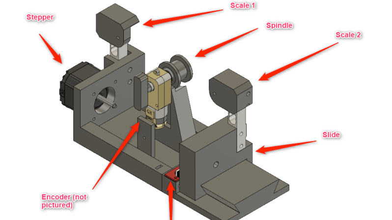
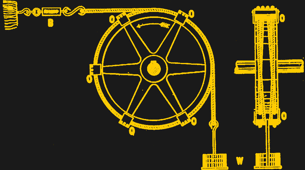 He then goes on to research methods of measuring the motor’s output where he discovers the Prony Brake which leads to the Rope Brake Dynamometer. This is where things get interesting and [Gerrit Coetzee] goes on to hack his own version of the machine. The idea is to have a rope wound to the wheel that is powered by the motor. With one end of the cord attached to a spring scale and the other end to a suspended weight, the motor speed affects the force on the spring scale. This change in force measured by the scale can be used to calculate the power output by the motor.
[Gerrit Coetzee] goes on to replace the weight with springs and the scale with an electronic load cell while using a stepper motor to stretch the cord thereby adding the requisite tension to the string. We thought this was a very elegant solution where the entire experiment could be controlled electronically.
This is a work in progress through the writeup is an excellent example of how to tailor a traditional experiment to the modern times. We have seen similar investigations for larger salvaged motors and dynamometers with lots of sensors.


Amazing how simple it really is to measure torque at speed.
Wouldn’t measuring the force on the rope be dependent on the friction of the rope around the wheel.
I would have thought having the strain gauge between the motor housing and its mount would be a more appropriate place to measure the torque.
Maybe I need to research this a bit more
Sure! But that is the measure of torque. It doesn’t matter where you measure it on the rope, as long as it doesn’t interfere with the curved part around the wheel.
You could put strain gauges on the motor mount, but you would need several in order to determine torque, and you need to possibly measure a vector force depending on how the motor’s shaft is loaded: not all of the forces on the motor mount are torque. There will usually be a static linear component to the force, and it does not contribute to motor load as it is carried by the bearings.
Measuring rope tension (if you want a torque measurement) is better because the rope attaches directly to the shaft at a known radius. All of the friction of the rope (i.e. braking torque) is directly visible as a change in the difference in rope tension observed at end of the rope, which is trivially measured with a pair of load cells.
It seems incorrect that the speed of the motor changes the force transferred to the rope. Dynamic friction does not linearly increase with speed. If it did then car brakes would be far more effective at higher speeds. It seems more reasonable that increasing the force at a given RPM until the motor cannot maintain that RPM will find the largest torque the motor can produce at that RPM.
Interesting history: https://en.wikisource.org/wiki/1911_Encyclop%C3%A6dia_Britannica/Dynamometer
I’m not directly familiar with the apparatus, but the weight always exerts the same force regardless of displacement, while the spring he replaced it with provides a force that roughly proportional with displacement. This definitely gives me concerns about spoiling the measurements with unaccounted-for factors.
That’s why he has two load cells. They will measure from each end of the string.