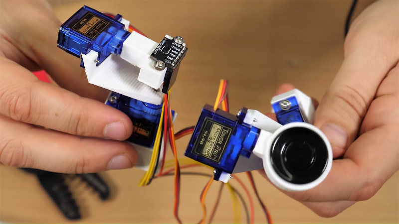
Sometimes the best you can say about a project is, “Nice start.” That’s the case for this as-yet awful DIY 3D scanner, which can serve both as a launching point for further development and a lesson in what not to do.
Don’t get us wrong, we have plenty of respect for [bitluni] and for the fact that he posts his failures as well as his successes, like composite video and AM radio signals from an ESP32. He used an ESP8266 in this project, which actually uses two different sensors: an ultrasonic transducer, and a small time-of-flight laser chip. Each was mounted to a two-axis scanner built from hobby servos and 3D-printed parts. The pitch and yaw axes move the sensors through a hemisphere gathering data, but unfortunately, the Wemos D1 Mini lacks the RAM to render the complete point cloud from the raw points. That’s farmed out to a WebGL page. Initial results with the ultrasonic sensor were not great, and the TOF sensor left everything to be desired too. But [bitluni] stuck with it, and got a few results that at least make it look like he’s heading in the right direction.
We expect he’ll get this sorted out and come back with some better results, but in the meantime, we applaud his willingness to post this so that we can all benefit from his pain. He might want to check out the results from this polished and pricey LIDAR scanner for inspiration.


The problem is the FOV of the TOF module is surprisingly wide.
He would probably several orders of magnitude of improvement with a 20-30mm long bit of heat shrink over the aperture.
Or a straw hot melted to it. Still the measurement is +/- 2mm I found. Not that great. Also, each measurement is like 30ms or worse. Depending on the cloud size you are shooting for it might be too slow.
If you’ve got any camera film tubs or similar laying around.
A pin hole camera with nine LDRs or LDTs works pretty good for scanning a large area. Even better if you make four. red, green, blue and white for comparison.
I’ve never tried it with a optical mouse sensor that may be better and easier to interface.
This is a project to produce a depth image, not a brightness or color image.
This is really cool. Plenty good for glitch aesthetics. I might take a stab at this myself…
For ultrasonic ranging, the issue is easy to spot. It’s wide angle of the transducer. They are used in cars and they have to “see” around the whole bumper. [bitluni] would have to make it more directional, which is something I have no experience with (ultrasound accoustics, changing the direction of sound wave on such frequency etc…)
For optical TOF, as Daren Schwenke said, FOV is the issue. That can be handled easier than for accousitc (at least I know how to do so) and I believe there should be more dense point-cloud, to be able to see something. Maybe if you do more post processing and delete furthest points, something can be seen from raw data.
Maybe stereoscopy can help.
Good luck with the development!
Too few points!
Around the 1:00 mark in the video, it was interesting to see a sample of mech engineering / “CAD-style” workflow done in Blender. I’ve always used Fusion 360 or other parametric systems for my design work, and the times I’ve tried to learn Blender, it felt kind of floaty. Good for artistic stuff, but I didn’t really see myself using it for making anything with rigorous dimensional requirements. Seeing that timelapse, however, convinces me that the trick is at least possible.
I’m currently designing my newest 3D printer in Blender (almost finished), however I see the benefit of a real CAD tool, e.g. when you try to move parts of the machine like the hotend carriage of my corexy system. The only reason that I still use Blender:
1. I have no idea which CAD product is both suitable and affordable for a hobbyist
2. I’m very familiar with Blender, so for getting things done right now it’s the best option for me
Feel free if you have suggestions on good and affordable CAD software.
OnShape, runs in your browser no installing necessary, powerful and somewhat intuitive, lots of help, free for hobbiests as long as you don’t mind your projects are publicly viewable and can be copied by anybody there, personally in exchange for a free tool with OnShape’s features, that’s a sacrifice I readily make.
If not OnShape, then Fusion 360 is the other competitor. Has the same issues (cloud based storage), but it runs in a full client, not in your browser. Offers LOT of functions and is free for makers, students and non profit work.
Okay so now I get to feel smug as hell for apparently correctly foreseeing the kind of (pretty bad) results either of these ranging technologies would have as part of a DIY 3D scanner, without ever actually lifting as much as a screwdriver. Which is nice and all that but unfortunately I don’t have any better ideas of how to actually make it usable without resorting to multi-hundred bucks mini-LIDARs and such. I’ll be the first to cheer him on though and applaud if he gets anywhere near reasonably useful results…