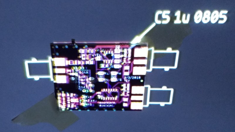
[Ted Yapo] has big ideas for using Augmented Reality as a tool to enhance an electronics workbench. His concept uses a camera and projector system working together to detect objects on a workbench, and project information onto and around them. [Ted] envisions virtual displays from DMMs, oscilloscopes, logic analyzers, and other instruments projected onto a convenient place on the actual work area, removing the need to glance back and forth between tools and the instrument display. That’s only the beginning, however. A good camera and projector system could read barcodes on component bags to track inventory, guide manual PCB assembly by projecting which components go where, display reference data, and more.
An open-sourced, accessible machine vision system working in tandem with a projector would open a lot of doors. Fortunately [Ted] has prior experience in this area, having previously written the computer vision code for room-scale dynamic projection environments. That’s solid experience that he can apply to designing a workbench-scale system as his entry for The Hackaday Prize.


Seems like this would be a whole lot easier and 90% as useful if he ditched the projector stuff and just did an HUD overlay onto a USB microscope image.
How much of your bench can you see with a microscope at any given time?
pretty much everything i’m interested in/working on…
Sounds like the perfect use-case for smart glasses. Something akin to the hmt-1z1, vuzix m100, or even google glass.
I periodically think of exactly this… or the lack of it… when working on boards. I’ve daydreamed of “Ok google, show me C15”. “Ok google, what type of component is R12?”, etc. *sigh*… someday…
Your “someday” was essentially in 1992. Check out the Contact Systems CS-400 line of Through Hole Component Locator Machines. Essentially, the model D that came out in 1992 could be easily adapted to do exactly what you mention.
http://www.versatecsolutions.com/csi_400e_products_history.html
Nowadays, we do have software that does this but without voice recognition. At the EMS I work for, we use Aegis Fusion as our Manufacturing Engineering Software system. The CircuitCAM software that is a part of the software suite creates intelligent digital representations of a PCBA for work instruction use by operators in all steps of manufacturing. Type in C15 in the “visual aids” search box and it will highlight the part on the board in both a zoom view and a full board view while showing all the details for that location. For assembly and debugging, it is very powerful. The schematic and CAD data can also be embedded or linked, so test technicians only need one interface to fully troubleshoot boards.
Check out Paul Daniels flexbv
https://www.youtube.com/watch?v=jOJlCzQX9cs
“Okay Google, please overlay the power supply distribution of this circuit board.”
Google: “That board is DRM’d and under an NDA, as you are not authorized to work on that board, I am notifying the lawyers of the manufacturer.”
now it’s possible — https://www.inspectar.com/
Bice – & perhaps for fault-finding / repair- probe around on the board, & the voltages/waveforms etc are pulled up from the schematics/SPICE/ Board layouts etc & then overlayed (in different colours etc), all referencing the pin of the component you are probing.. – winner in my book – the Human Pogo-Pin :)
(‘Nice’) – (really shouldn’t wear my Ski-Gloves indoors..:)
Looks a lot like this: https://lampix.com/products/lampix