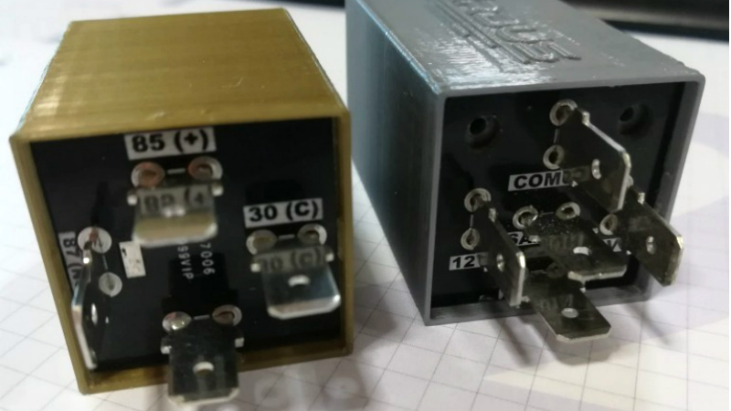
Automotive components that have a hidden secondary function are usually limited to cartoons and Michael Bay movies, but this project that [Jesus Echavarria] created for a client is a perhaps as close as we’re likely to get in the near future. The final product certainly looks like a standard automotive relay, but a peek inside the 3D printed case reveals a surprisingly complex little device. It’s still technically a relay, but it uses a PIC microcontroller to decide when it should activate.
 [Jesus] was given the task of creating a device that would fit into the relay box of a vehicle, and serve as a battery monitor to fire off at different voltage set points. The client also wanted the ability to configure such things as how long the device would wait before enabling and disabling the alarms once the voltage threshold has been passed. After showing the client an oversize prototype using a PIC16F88 and switching regulator, he got the OK to move on to a smaller and more cost-effective version.
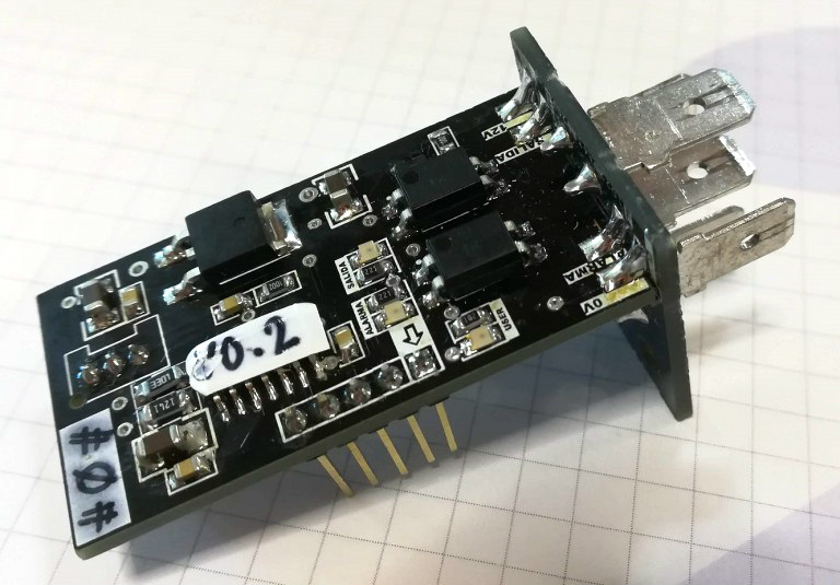
The final hardware makes use of a 78M05 500 mA linear regulator, a PIC16F1824 microcontroller, and a pair of AQY211EH solid state relays. The standard five pin layout used for automotive relays allows the monitor to get power from the vehicle’s battery while providing two output channels that can be switched on and off from the microcontroller. [Jesus] says an agreement with the client prevents him from sharing some elements of the project (like the firmware source code), but he gives enough information that it shouldn’t be too hard to spin up your own version.
With the addition of something like an ESP8266, this could be an easy way to retrofit an older vehicle with “smart” features. As an example, it could potentially allow for controlling the car’s headlights and horn over Wi-Fi. Or you could hack together a theft deterrent system that refuses to power on the starter or fuel pump unless your smartphone enables the relay first.


But why the PIC? It’s ancient and has memory banking that drives me to the insanity. You could’ve used modern STM32 micro that has GCC and OpenOCD support.
Why not a PIC? Use what you know.
PICs have a long history on the industrial area, require a minimal amount of external components and are cheap as dirt. If you already know how to use them and have the necessary programmers, they are a great option.
Makes a lot of sense if you’re connected to a battery (even a car battery) 24/7. That series 1824/1825 has a sleep current of 20nA (okay, absolute best case, but still…). It’s a very capable little chip with EEPROM and 8 available ADC pins in a 14-pin package. I usually choose the 1825 for the extra memory.
Nowadays you can even program it using Microchip’s cloud IDE (so you don’t even need to have a compiler installed) – https://mplabxpress.microchip.com/mplabcloud/ide
Select File->New-Project and in the pop-up window select PIC16F1824 under “Categories – Microchip Examples”, then select “Next”, followed by “Finish” and you’ll find yourself with a complete project, pre-populated with automatically built support files (interrupt, timer, PWM, memory and adc).
Except that someone is using a 78M05 which is anything but low quiescent power (3.2mA typ – 6mA max). So no that is not the explanation.
I was going to mention that those little buck switching regulators can be had for like 50 cents a pop or so and they are near 95% efficient and about the size of a TO220 device. Everybody does things a bit differently. What is sad is he is not sharing any of his secret sauce. That lack of transparency makes me wonder about the entire project, but I always complain when HAD essentially runs a commercial.
He replaced it with a switching regulator for V1.1
“So, I decide to change linear regulator with a switched one. I choose the RECOM R-78E-0.5. Its a low cost switching regulator, with a efficiency up to 95% and pin compatible with 78 series regulators.” from the hackaday link
You care about bank switching only if you’re programming in assembly, and I don’t think many people do that. There is MPLab and MikroC, so you write code in C and compiler takes care of the rest. By the way, both those IDEs look very nice and modern, compared to ancient looking Arduino IDE. Microchip has vast selection of micros, from 8 bit to 32bit they introduce new ones all the time, and support for older models lasts for many years. That’s why they’re quite common in industrial/automotive enviroments.
Because it’s overkill for the job at hand. If one can save cost by choosing a micro controller that is just up to the task using all the resources it has. The vast selection of PIC micro controllers allows you to select devices that only have the resources you need (mostly) and get a lower price based on that.
I like to use the larger version of the used chip, the 16F1827 for prototyping. I used it to create a led light that uses pwm to for use in a boost converter, and a button. I then found the mcu that would have just enough pins to do this and came to the 16F18313, an eight pin soic device. I’ve been optimizing for size for a while and got the pcb really tiny.
I really wouldn’t want a 32 bit mcu hogging up the pcb space with functions I’d never use in some applications. Of course 32 bit has its place, I used a PIC32 as a digital oscilloscope for example, sampling at 3x 6MHz, pushing 18MB of data per second through the usb2 interface.
Not just an ‘ancient’ pic but also a 7805 linear regulator.
But if you give jesus a task he’s bound to go old school I guess?
(I know, low hanging fruit, I’m sorry already.).
I have this feeling there was something about such solder PCB-to-PCB connections developing cracks over time… Anybody could elaborate?
I’m looking at a 40+ year old Fluke unit with such that works fine, amongst others. That method CAN fail a number of ways, because you can get some pretty significant loads on the solder joints. I have never seen the solder fail (other than when the solder job was defective to begin with). The mode I have seen in a few cases is the trace separating from the substrate. I should imagine that this needs to be planned for when vibration or shock is an issue, possibly with full through vias at each solder joint to spread the load through the board, but this is conjecture. I have used this joint configuration a few times without a failure, but never in an impact or vibration application.
That kind of interconnection is used very often in industry in commercial products. The best designs have a tongue and groove setup to help support and align the boards.
Solder has no strength so will crack under stress with typical automotive vibration, but providing the circuit board fits snugly and is held in supportive tracks in the enclosure, then I’m sure solder cracking issues won’t be a problem anytime soon.
Solder has no strength? I beg to differ. I mean stained glass windows are soldered aren’t they? As are many things outside electronics like lead roof cladding and copper pipes carrying natural gas.
Not that you aren’t right that you should support it in cases like this.
But I think solder has some strength, and in fact with electronics you run more risk of the solder pulling the copper traces of a PCB than actual breaking of solder in most cases in my experience. Although I don’t have much high-vibration experience I must add. And of course now we are well into moving to lead-free soldering which often means more crack-prone solder I’m told.
I’ve used solder connections on board edges a few times without issue, though one does need to consider vectors on the primary mechanical forces; compression, tension & shear. This is one public example I did first around 2002 and some of these older modules sold s/h through eBay at higher than new retail when I was ill few years ago.
http://niche.iinet.net.au/more.html
As macona has mentioned the tongue/groove approach very helpful. In reference to the black Bosch relay holder on my link the two boards at right angles used a slot with friction fit to ensure tight connection. Once you get past some manufacturers confusion between milling, routing passes and outline cutting it works very well. I used a solder line underneath to hold the edges together but, ‘tangs’ on the PCB offer the primary protection against bending moment and vibration with the solder line on both sides further spreading loads. My 2002 version still in use on some older cars to this day :-)
Large vias and dove tailing in both mating boards would help alleviate any cracking that might occur with only pads. It would use much more solder but would make for a relatively strong joint.
Hopefully the inside of the housing hase grooves to hold the PCB so it won’t experience any stress due to vibration
Actually common to see similar solutions in big ol’ automotive relay housings.
One especially common one is retrofit comfort indicators, where many kits are based on the VW one with part no: 000-953-227-A
I added it to my 1999 SAAB by adding a Arduino to the DICE module https://hackaday.io/project/158595-3-blink-modification-for-saab-9-5
Yes, that anti-theft functionality would be superb! Wait, what? What if you lose your phone, or simply run out of juice?
I’m struggling to imagine the use case for wifi-enabled headlights or horn. Perhaps bluetooth but even that is kinda stupid.
Herbie!
Keep the original relay in your glove box or console. If your phone is lost or dies you can easily put the original back in to make your car work again.
Interesting place to hide a…tracking device.
just after I hit enter I saw this…. yup… available only at local Autozones near Laurel Md.
Nice one! I’m working on the same thing, but using a esp8266 on the OBD port.
Got 50 devices ready for a battery monitoring test.
I feel this is relevant.
https://www.youtube.com/watch?v=pZ301QEoo9Y
wow… just found a great way to hide a gprs based tracker.
100V SSRs seem like a good idea. At first I was worried about the 35V maximum input voltage for the voltage regulator, and the 40V max Vds of the MOSFET, but there is no need to worry about that, because the MOSFET will die from Vgs overvoltage when the first spike over +/- 20V comes along. At least give the poor thing a zener across the gate-source or pick a type that has one internally.
If the device uses so little current, why not simply use a diode for reverse polarity protection? How about a small series resistor and a TVS for occasional spikes?
Someone who calls himself a professional did this? For actual money?
I see what it does, but… Why? What can it be used for?
Like those above mentioning GPS trackers, my first thought was how that’s a great source of power that’s out of the way (not taking up cigarette outlets). I’ve got an esp8266 board in my vehicles just to announce when they’re home to my home automation setup. I ended up attaching them to the OBD port for power so I wouldn’t have to make modifications to the vehicles, but this should work as well.
Not sure how well GPS would work under a hood, but I dunno.
Assisted-GPS might work better.
You might find some of the mostly plug-and-play upgrades available for the components in a DeLorean’s electrical compartment interesting. Dave McKeen/BitSyncMaster has made some interesting ones and I have a few of them in my vehicle: https://dm-eng.weebly.com/
Quick explanations of his stuff:
– HVAC LED panel replaces the old incandescent-lit display with SMD LEDs that are crisper with more vibrant colours but less watts
– Solid State RPM Relay replaces a rather common failure point in the car while also having features like better fuel pump timing to give you quicker starts & workaround fixes if you have poor resting fuel pressure
– Solid State Fan Fail unit gives a separate fuse per fan, returns the functionality of the “fan fail” light that most users disable while making it flash to grab your attention, and also lights it up if only one fan has failed
– Solid State Fan Relay adds a delay to both turning on and turning off the cooling fans, to avoid too big a voltage sag when your compressor turns on and preventing cycling the fans if your compressor is cycling too quickly
– Microprocessor Idle ECU swap gives much smoother idling, slightly improved fuel efficiency and better AC performance
– Dome Light Dimmer replaces the normal dumb relay with a delay dimmer, with optional blinking parade mode and auto-off timer if you accidentally/purposefully leave the door open