We’re used to loudspeakers as circular components with a paper cone and a big magnet inside which is suspended a coil that is connected to our audio amplifier. But moving-coil speakers are not the only way to create sound from electricity, there are one or two other weapons in the audio designer’s arsenal.
One of the more spectacular and entertaining is the plasma speaker, and it’s one [Marcin Wachowiak] has been experimenting with. A continuous plasma in the form of a discharge between two electrodes is modulated with an audio signal, and the resulting rapid changes in the volume of plasma creates a sound. The value of a plasma speaker lies in the exceptionally low size and mass of the element producing the sound, meaning that while it can only effectively reproduce high frequencies it can do so from a much closer approximation to a point source than can other types of tweeter. For this reason it’s beloved of some audiophiles, and you will find a few commercially produced plasma tweeters at the high-end of the audio market.
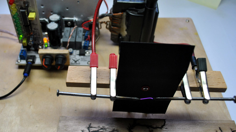
[Marcin] isn’t in it for the audiophilia, instead he’s interested in the properties of the plasma. His plasma speaker does do the job well though, and in particular he’s put a lot of thought into the design of its drive circuit. At its heart is the ubiquitous TL494 PWM controller that you may be more familiar with in the context of switching power supplies, this one applies the audio drive as PWM to the gate of a MOSFET that switches the primary of a flyback transformer. He’s added refinements such as a gate discharge circuit and a second primary winding with a freewheel diode.
The result is an effective plasma speaker. It’s difficult to judge from his YouTube video below the break whether he’s achieved audiophile purity, but happily that’s not the point. We’ve shown you a few other plasma speakers in our time, if the subject interests you then take a look at this rotating plasma vortex, or a version using a 555 timer.


I wonder if you did an FFT of your audio and then had tuned helmholtz resonators for each band with the plasma electrodes for each band inside the corresponding resonators if you could get a richer sound?
What is the most effective, and in regards to time (I’d guess processing speed and memory capabilities), way to implement FFT or FHT on an IC? I’d guess an assembly process on an IC, though can’t visualize. The easiest to read already performed appears to be a microcontroller like an Arduino. Are there dedicated IC’s that can perform the DSP as I can’t imagine an analog method at the moment since seems digital by mathematics design?
A chain of filters tapped at the right points may be enough for an analog version.
For something like a bargraph display you can run a bunch of narrow band filters on a Cortex M3. FFT will be slower, or low resolution, or require a more powerful CPU.
What is a “freewheel diode” ?
I see he added two winding’s on the former.
One is a replacement primary winding most likely because the original primary would work in the range of 90V to 160V and the new primary winding only requires 20V.
The other added winding I would call a secondary winding for spike suppression. This could have been done with passive components and no power but the way he has done makes the drive circuit more power efficient.
The schematic is well thought out and designed.
A freewheel diode is just a diode across an inductor that prevents inductive voltage spikes if you suddenly shut the current off. They have the magical ability of conserving the magic smoke in surrounding doodads.
I wonder what the power requirements are using math for the size of arc required to create down to 20Hz? I wonder if there is a threshold where the plasma doesn’t need to be emitting visibly also and sound can be produced? Seems like.
“The dominant frequency of thunder energy is in the 100 Hz range. Thunder occurring in the infrasonic range (below 20 Hz) is inaudible to humans.”
You’d need to go big.
I wonder if there is a threshold where the plasma doesn’t need to be emitting visibly also and sound can be produced? Seems like.
No plasma, no carrier. Without the potential, the gases are ionized but remain in gaseous state. Plasma is another (potential) state of matter.
So to produce the pressure wave, an electrostatic or electric transition state has to occur versus just a rotational and/or vibrational state change?
Seems something like a pulse modulation, or maybe combination band from a acoustic hailing device, could produce sound without a plasma that is visible from more a electromagnetic cavitation effect, albiet not the loudest. Kind of thinking since RF can produce heating without plasma, that a localized focused point could produce a pressure wave modulated in the audible range not just by the combination band being in the acoustic range.
Wouldn’t something similar with a magnetic transition state produce a pressure wave also or do both electric and magnetic transition have to occur?
Lower frequencies require larger size of the emitter. A long arc tends to wander around, which adds noise.
The sound is emitted because the plasma gets larger and smaller, so the plasma being visible is kind of a requirement. Or rather, a side effect of the requirement of a minimum current. Think of a class A amplifier. If you want +- 1A going into the speaker, the class A amplifier requires at least 1A quiescent current.
I’m thinking it should be possible to increase the area by using several arcs, close enough to form the waves, but far apart enough not to jump across.
But the practical benefits of that would be fairly low. You need to trap the other phase and route it away to the bass port. Easy with classical cone speakers, not so easy when your medium is gas.
As a tweeter, the current design can be improved a lot by adding a horn.
Bass requires more than just speaker area, it requires speaker travel. That is why a tweeter barely has to move and requires a lot lower power handling, and a woofer has long throw and can use 10x the power.
It takes both because… volume. You can get bass at such low frequencies it will make you sick simply by twisting the blades of a fan blowing air (rotary subwoofer). Still, those are a lower range than most people are thinking when they think bass (it’s like 100-0 Hz), and beyond the target all but a select few target. I think the practical limit to generating bass on plasma speakers is going to be the noise, still you can filter it out if you start making boxes with either passages or objects (metal pipes) spaced just to selectively filter out the background noise the setup is generating… but why? Just pick the best setup for the range, and use a crossover network. Hell, I saw a youtube vid where the range the guy got out of a driver slapped onto a ceiling tile was really impressive. Do that for your mids, plasma for the highs, and a rotary for your ultra lows, and you’ll blow peoples minds with your setup that lacks a standard speaker.
Agreed. I’ve done some drivers that people might think of as odd.
I recall long ago a company was selling what looks like a ceiling tile from below. It was actually styrofoam. On the other side, it had cone shapes with thin styrofoam surrounding them to allow them to move a bit. Voice coils attached to the styrofoam and the spiders and magnets attached to a frame around the edge. Actually had a woofer, mid, and tweeter. It couldn’t get very loud, but for sound in an office, you don’t want or need high volume.
GreatScott just did a video with this IC also and demonstrated lower frequency generation:
https://www.youtube.com/watch?v=m-4sHRzexpQ
I recall reading about this in Popular Electronics back in the 60’s. Not a new concept, You also have a continueous background “sizzle” from the arc.
But it won’t be noticible if you make the carrier frequency one that’s above the range of human hearing.
There is a random aspect of this that has nothing to do with the carrier frequency.
Thanks admin for sharing this informative article.
Heres my plasma teslacoil
Running at 10.87mhz
https://youtu.be/7VGVDPuXhl0
The audio quality is a lot better than I what I normally expect from plasma. Is ti the higher frequency that helps?
I have to ask … Why 10.87 MHz
I am wondering also. Larger bandwidth capabilities for higher resolution of the full range of sound perceived can be produced?
Seems something like this could emit up to 10.87 MHz also I guess… so could emit ultrasound.
Wondering what the sound (pressure wave) capabilities are and if there is any nerve conduction pickup by the human body perceived as bone or typical ear drum conducting sound.
Heres my plasma teslacoil
Running at 10.87mhz
https://youtu.be/7VGVDPuXhl0