Spot Welding …Plastic?

Plastic milk bottles, when your project or prototype needs an urgent source of plastic, they are often the first thing to hand. Convenient and flexible, but strong at the same time and usually free, they’re the ultimate source of material in a pinch. However, when it comes to actually manipulating the HDPE plastic they’re made from, there’s often a challenge. It’s easy to cut, but not so easy to join. Conventional glues can have a hard time, making it difficult to bond.

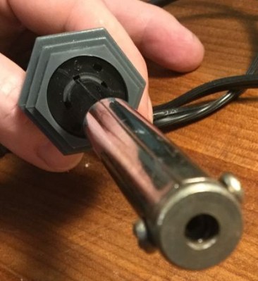
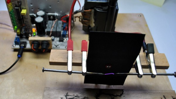
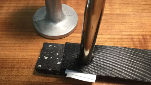
Enter [zimitt], and a spot welding solution for joining HDPE with ease. Ok, so ‘spot welding’ might be a little optimistic given the speed of this process, but it’s useful nonetheless. To heat the plastic, a cheap soldering iron is recommended. A low wattage, straight-to-the-wall one does well, especially as they commonly have the washer-style end shown in the picture. To protect the plastic from burning, a BBQ mat is used – they’re temperature resistant and usually made with a PTFE surface.

First, place the two sheets of plastic face to face and sandwich top and bottom with the BBQ mat. Apply some heat to the mat with the soldering iron then, after a few seconds, remove the iron and provide pressure with a flat object to bond the plastic. [zimitt] used an espresso tamper for this which was ideal.

The results are impressive, and [zimitt] experiments with different plastics as well. Of course, you should exercise caution when attempting anything like this, given the health risks present when heating up different types of plastic.

HDPE is easy to recycle at home, and we’ve seen a lot of great uses: a plastic joiner’s mallet, plastic tiles, and even a filament extruder for 3D printing.

A Plasma Speaker Using A TL494

We’re used to loudspeakers as circular components with a paper cone and a big magnet inside which is suspended a coil that is connected to our audio amplifier. But moving-coil speakers are not the only way to create sound from electricity, there are one or two other weapons in the audio designer’s arsenal.

One of the more spectacular and entertaining is the plasma speaker, and it’s one [Marcin Wachowiak] has been experimenting with. A continuous plasma in the form of a discharge between two electrodes is modulated with an audio signal, and the resulting rapid changes in the volume of plasma creates a sound. The value of a plasma speaker lies in the exceptionally low size and mass of the element producing the sound, meaning that while it can only effectively reproduce high frequencies it can do so from a much closer approximation to a point source than can other types of tweeter. For this reason it’s beloved of some audiophiles, and you will find a few commercially produced plasma tweeters at the high-end of the audio market.

[Marcin] isn’t in it for the audiophilia, instead he’s interested in the properties of the plasma. His plasma speaker does do the job well though, and in particular he’s put a lot of thought into the design of its drive circuit. At its heart is the ubiquitous TL494 PWM controller that you may be more familiar with in the context of switching power supplies, this one applies the audio drive as PWM to the gate of a MOSFET that switches the primary of a flyback transformer. He’s added refinements such as a gate discharge circuit and a second primary winding with a freewheel diode.

The result is an effective plasma speaker. It’s difficult to judge from his YouTube video below the break whether he’s achieved audiophile purity, but happily that’s not the point. We’ve shown you a few other plasma speakers in our time, if the subject interests you then take a look at this rotating plasma vortex, or a version using a 555 timer.

Continue reading “A Plasma Speaker Using A TL494”

Hackaday Links Column Banner

Hackaday Links: August 5, 2018

Here’s something of historical interest. The daughter of Terry Holdt, project manager for the 6502, cleaned out a garage and found shelves full of MOS Technology binders, test results, notes, instructions for processes, letters to customers, and datasheets full of errata. Some of these documents have been posted on Twitter, and efforts are underway to collect, scan, upload, and preserve them. In the distance, a man in a fabulous suit is screaming, ‘donate them to the Internet Archive’.

This is a link to Defcad, the repository of 3D printable files for weapons. Under an agreement with the US Department of State, Defcad was set to go online on August 1st. This caused much handwringing in the tech journalist thoughtspace, with reporters calling to end the first amendment because they don’t like the second. Alyssa Milano chimed in. Defcad was ordered shut down by a federal judge in the western district of Washington before going live.

As you may well be aware, Printrbot ceased operations last month. It’s sad to see them go, but they made some acceptable machines and were really pushing the boundaries of what was possible with their infinite build volume prototype printer. But what about all those existing printrbots in the wild, you might ask. Well, good news for anyone who hasn’t changed their hotend over to an E3D yet: Ubis is going to be selling hotends. Get ’em while they’re hot (or not, I don’t know how this pun works).

File this one into the ‘awesome government auctions’ category. The city of Longmont, Colorado decommissioned their tornado sirens last year because they ‘self-activated’ and malfunctioned. These sirens were put up for auction, with a winning bid of $526. Someone bought the most annoying thing imaginable for just over five bills. The world of government auctions is amazing.

How To Run A Clock For A Century

What’s going to keep a clock running for a century, unattended? Well, whatever’s running it will have to sip power, and it’s going to need a power source that will last a long time. [Jan Waclawek] is looking into solar power for daytime, and capacitors for nighttime, to keep his clock running for a hundred years.

This project carries on from [Jan]’s previous project which looked at what kind of power source could power the gadgets around his house for a century without needing intervention – ie., no batteries to replace, no winding etc. [Jan] whittled his choices down to a combination of solar power and polypropylene film capacitors. Once the power had been sorted, a clock was chosen in order to test the power supply. The power consumption for a clock will be low during the night – it would only need a RTC circuit keeping track of the time – so a few low-leakage capacitors can be used. When daylight returns or a light is switched on, the solar circuit would power the clock’s display.

At the moment, [Jan] has a proof of concept circuit working, using the ultra-low-power microcontroller on a STM32L476 DISCOVERY board and a few 10 μF 0805 size capacitors, when fully charged by the solar panel, the clock’s display lasts for about two minutes.

Take a look at [Jan]’s project for more details, and check out his previous project where he narrowed down the components for a hundred-year power supply. [Jan]’s prototype can be seen in action after the break. Also take a look at this master clock that signals slave clocks and runs for a year on a single AA battery.

Continue reading “How To Run A Clock For A Century”

VCF West: Adding A Front Panel To The 6502

When you think about vintage computers from the 1970s, the first thing that should spring to mind are front panels loaded up with switches, LEDs, and if you’re really lucky, a lock with a key. Across all families of CPUs from the ’70s, you’ll find front panel setups for Z80s and 8080s, but strangely not the 6502. That’s not to say blinkenlights and panel switches for 6502-based computers didn’t exist, but they were astonishingly rare.

If something hasn’t been done, that means someone has to do it. [Alexander Pierson] built The Cactus, a  6502-based computer that can be controlled entirely through toggle switches and LEDs.

If you’re wondering why something like this hasn’t been built before, you only have to look at the circuitry of the 6502 CPU. The first versions of this chip were built with an NMOS process, and these first chips included bugs, undefined behavior, and could not be run with a stopped clock signal. These problems were fixed with the next chip spin using a CMOS process (which introduced new bugs), but the CMOS version of the 6502 would retain the contents of its registers with a stopped clock signal.

The specs for the Cactus computer are what you would expect from a homebrew 6502 system. The chip is a WDC 65C02S running at 1MHz, there’s 32k of RAM and a 16k EPROM, dual 6551s give serial access at various baud rates, and there are 16 bits of parallel I/O from a 65C22 VIA. The ROM is loaded up with OSI Basic. The real trick here is the front panel, though. Sixteen toggle switches allow the front panel operator to toggle through the entire address space, and eight flip switches can set any bit in the computer. Other controls include Run, Halt, Step, Examine, and Deposit, as you would expect with any front panel computer.

It’s a fantastic piece of work which I missed seeing at VCF East so I’m really glad [Alexander] made the trip between coasts. Cactus is truly something that hasn’t been done before. Not because it’s impossible, but simply because the state of the art technology from when the 6502 was new didn’t allow it. Now we have the chips, and the only limitation is finding someone willing to put in the work.

Custom Designed Keyboard Needs A Custom Made Metal Case

It’s hardly news that mechanical keyboard users love their keyboards.  When it comes to custom keyboards, though, [Cameron Sun] has taken things to the next level, by designing his own keyboard and then having the case custom milled from aluminum.  If a Macbook and an ErgoDox had a baby, it would look like this!

[Cameron] had been using a 60 percent keyboard (a keyboard with around 60% of the keys of a standard keyboard) but missed the dedicated arrow keys, as well as home/end and pgup/pgdown keys. Thus began the quest for the ultimate keyboard! Or, at least, the ultimate keyboard for [Cameron.]

Keyboards begin and end with a layout, so [Cameron] started with keyboard-layout-editor.com, a site where you can create your own keyboard layout with the number of keys you’d like. The layout was a bit challenging for [Cameron] using the online tool, so the editing was moved into Adobe Illustrator. Once the layout was designed, it was time to move on to the case. Wood was considered, but ultimately, aluminum was decided upon and the basic shape was milled and then the key holes were cut using a water jet.

An interesting addition to the keyboard were three toggle switches. These allow [Cameron] to choose a modified layout for use when gaming, and also to move some of the keys’ locations so that one side of the keyboard can be used for gaming.

Custom keyboard layouts are getting more and more popular and there are lots of DIY cases to hold those layouts. [Cameron] has upped the ante when it comes to cases, though. If you’re interested in building your own keyboard, we have you covered with articles like The A to Z of Building Your Own Keyboard. If you’re looking for more custom cases, perhaps a concrete one is what you want?

Via Reddit.

Teardown Of A Fingerprint Padlock

We wouldn’t mind tearing down a fingerprint scanner, but we hate to bust up our expensive laptop or cell phone. [Julian], however, got a hold of a fingerprint scanning padlock and was willing to tear it apart for our benefit. The video appears below.

The padlock is a simple enough little device with a cable lock instead of a solid metal shackle, although we have seen similar devices with traditional shackles. Initially, the lock’s fingerprint storage is empty and it will open for any fingerprint. The first task is to set an administrator fingerprint. You’ll need that fingerprint to set up other fingerprints or to reset the unit. Of course, what we are really interested in is what’s inside.

Continue reading “Teardown Of A Fingerprint Padlock”