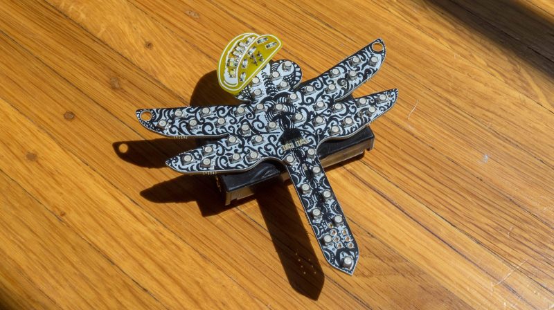
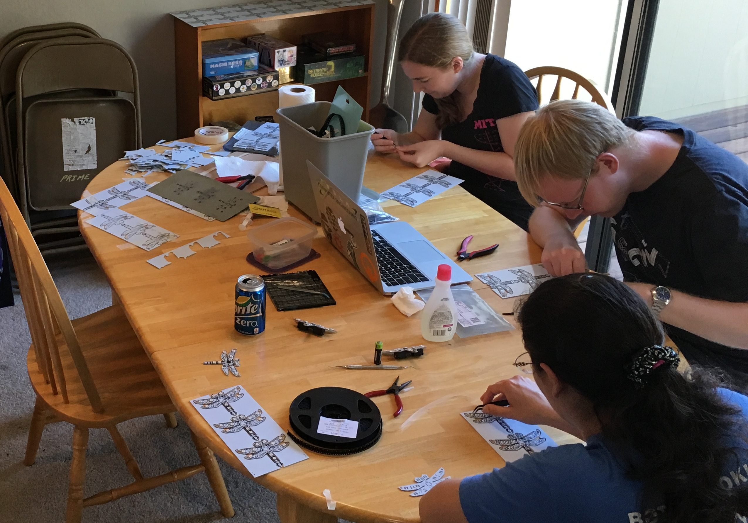
A couple years ago I got into making electronic conferences badges by building a device for DEFCON 25 shaped like a dragonfly. Like all badges the most important design factor was quite literally how flashy it was, and two years ago I delivered on that with ten RGB LEDs. At the time I planned to hand-assemble each and every of the 105 badges at my kitchen table. Given those constraints, and a desire for electrical and programmatic simplicity, I landed on using APA102s (DotStar’s in Adafruit parlance) in the common 5050 sized package. They were easy to place, easy to design with electrically, simple to control, and friendly to a human pick-n-place machine. Though by the end of the production run I had discovered a few problems, the APA102s were a success.
This year I made a new and improved version of the dragonfly, but applying my lessons learned led me to choose a very different LED architecture than 2017. I swapped out the smart LEDs for dumb ones.
When starting a new project I find it’s helpful to to clearly articulate a goal. In the first year the goal was “learn about building more than one of something”, a skill that can be quite a struggle! This year’s goal was “learn how to do things as if I was building a product for real.” Fortunately it turns out I’m not the only one around here who’s interested in that process and I had a lot to learn. To meet that goal the plan was to build 500 badges and get them manufactured and assembled by a real overseas production facility, a process which warranted new design considerations.
Let’s do some quick math. In 2017 each APA102 cost me $0.13 (purchased on eBay) and each unit had 10 of them, so that’s $1.30 in LEDs per badge. Not bad! The LEDs were pretty much the headline feature of the device and it was worth some money to do it right. But this year I obviously needed more LEDs. Last time I was bound by the practical reality of hand placing every LED which put a hard limit on the number of parts per board I was willing to use, but for 2018 I had already decided this wouldn’t be the case. So how many LEDs should I use?
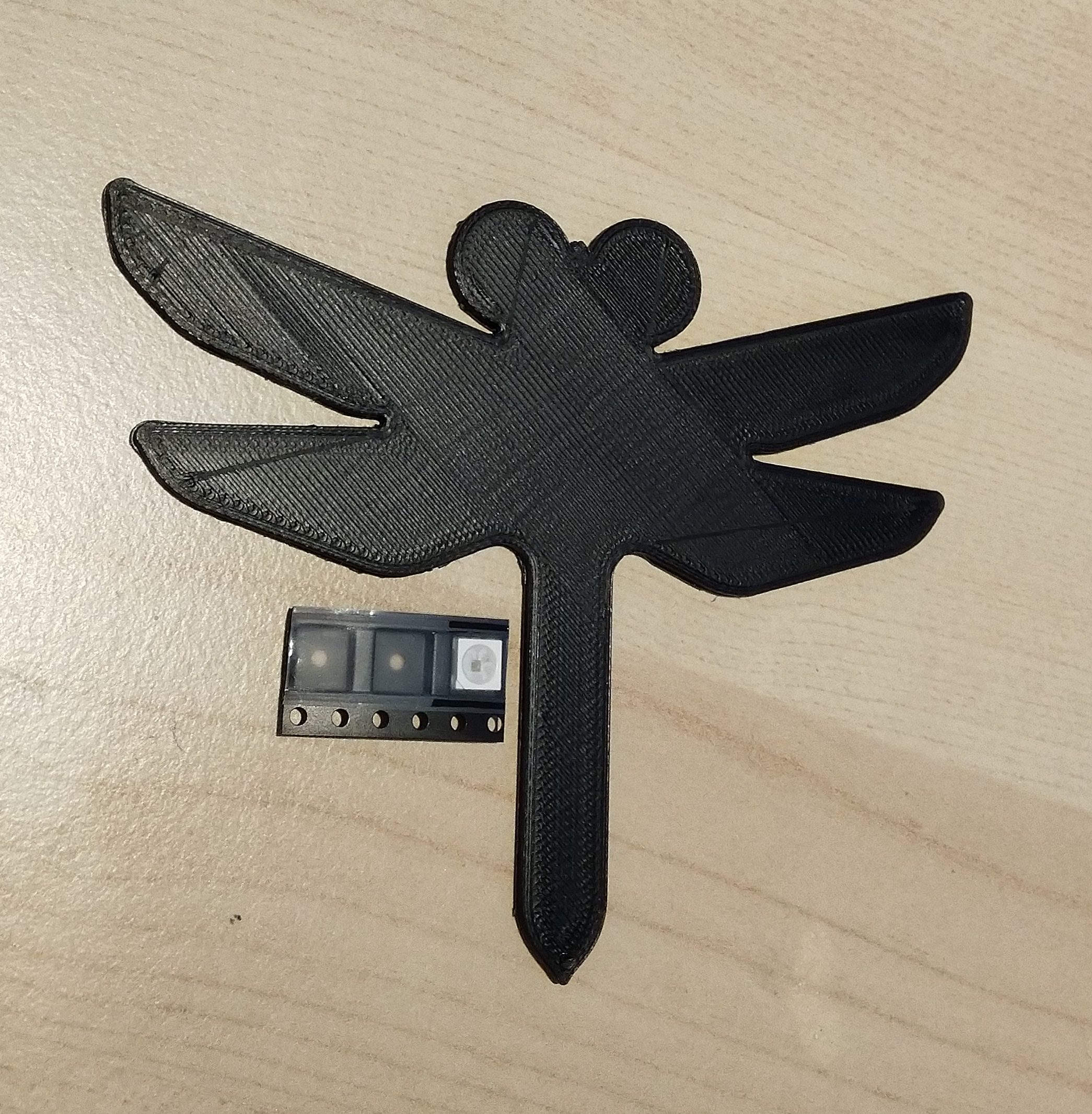
Obviously I should aim for a couple hundred! Well…as you can see in the image on the right a hundred LEDs won’t fit. How many will? After some non-scientific playing with a printed mockup of the design it seemed like with some adjustments maybe around 50 would. There would be plenty of time to tune the number as I went so it was more important to begin estimating than it was to be exactly right at the start. If I used the same of APA102s at the same price (remember, this is a rough estimate) I was looking at about 50 * $0.13 = $6.50 of LEDs per board. Again, for the headline feature, not too bad. But maybe I could do better. Now that adding LEDs was basically free in terms of assembly time I wanted as many as I could get.
What about “dumb” LEDs without controllers? That should be an easy way to save money. A quick skim of DigiKey suggested that while I could get dumb RGB LEDs in a wide variety of packages they weren’t actually inexpensive. The cheapest were about $0.17 a piece in full reels. So I turned to my favorite site on all the internet and began researching. And researching. Even a cursory search showed significantly lower prices and I amassed an extensive table of pinouts, prices, packages and options. As you can see from the highlighted row in the table the part I chose was an astonishing $0.006 each. That’s 0.6 cents per RGB LED. Now we were down to a comical $0.30 of LEDs per board if I could get 50 on there. For the price of three APA102s I could populate an entire badge! But a microcontroller that will directly drive 50 RGB LEDs (or 150 channels) wasn’t going to be practical so I needed to figure out how to control them.
Under Control
There are lots of ways to drive LEDs. In the past I’ve used a particular 36 channel constant-current LED driver, the IS31FL3236, that I really liked though it was a little expensive at $2.24 in single quantity on DigiKey. That was significantly more than I spent on LEDs alone last year so definitely a no go. Plus it was QFN. But this year with higher quantity and professional assembly things are different. On DigiKey there was a price break conveniently at 500 pieces. (Can you guess why I decided to make that many badges?) This brought the price down to about $1.26 each. Plus, if a machine was doing the solder paste stenciling and part placement I didn’t care that it was QFN – in fact the small size would probably make my design easier! So how do I use a 36 channel driver to drive 150 channels?
First I decided to knock two off my arbitrary RGB LED quantity and aim for 48 LEDs to make a convenient multiple of 12 (as in 12 x 3 channel RGB LEDs). The controllers weren’t too expensive at quantity so the simplest option was to add four controllers to each badge. Using DigiKey prices, that bumps us past a couple more price breaks so each controller would cost a mere $0.95. With this architecture the LED cost per board looked like (48 * $0.006) + (4 * $0.95) = $4.09, a pretty decent savings over the cost with APA102’s! But it seemed wasteful to use so many LED controllers given the plethora of options for LED control. Could it be even better?
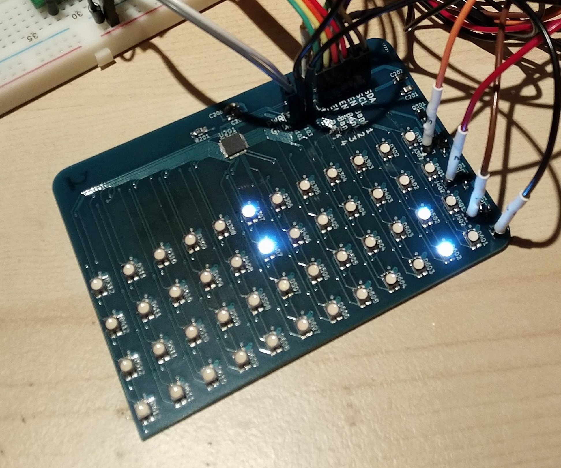
It’s a pretty common trick to use persistence of vision to scan a grid of LEDs and trick the human eye into seeing it as all on all at once. Alone a single IS31FL3236 drove each of its pins all the time (it didn’t timeshare) but maybe these two techniques could be mixed together. Each LED was common anode, meaning the high side of each R, G, and B diode was shared giving a convenient way to switch each entire LED on or off at once. I decided to go ahead and make a test board to see if this could work.
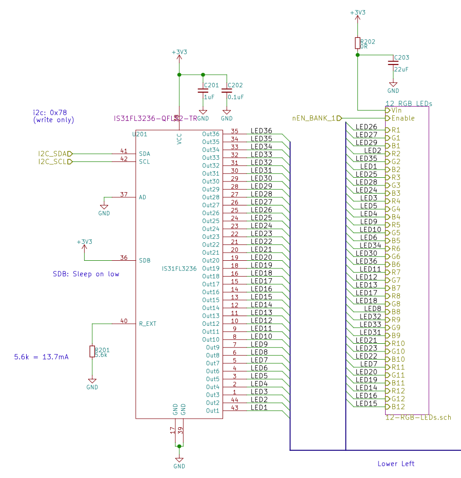
I divvied up the LEDs into four groups of 12 LEDs and connected each pin on the LED controller to a single leg of four LEDs (one in each bank). Instead of connecting the anode of each LED directly to a power rail they ran through a PFET. Each bank had a FET so they could be individually switched on and off by the microcontroller. After bodging around my backwards FETs and playing with the timing I got the test board to work, giving me a 12 x 4 RGB matrix driven by a single IS31FL3236 controller and four FETs.
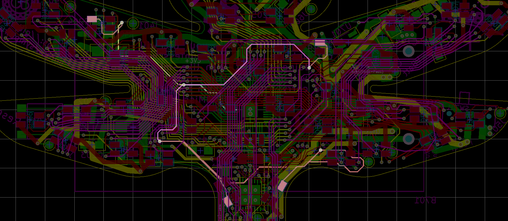
This was the architecture I ended up using for the final product. The only comment of note was how painful the final board layout ended up being. The combination of my naive routing strategy and bank switching topology meant that I had to route each trace to all four corners of my board. This pushed me up to six layers which became another case of a design decision made possible by higher volume — the jump to six layers from four only cost $0.60 per board.
So what was the final cost for LEDs and drivers per board? (48 * $0.006) + $1.26 + (4 * $0.054) = $1.764. A $0.50 premium, and a lot of code complexity, on the original 10 LED design yielded 48 RGB LEDs. After multiple iterations of the LED control state machine I was able to get the buttery smooth fades I was looking for and the final performance was very satisfying. Blinkenlights perfection.


“After bodging around my backwards FETs ”
Do you mean that you physically placed the FETs backwards (source and drain reversed)?
Or do you mean something else?
I designed the board incorrectly with source and drain reversed and ended up soldering the FETs in upside down to rearrange the pins :)
An easy mistake to make, I’ve done it too :-/
We’ve all been there. They also come reversed, just a matter of choosing the wrong package.
If you’re used to only working with N-channel MOSFETs it’s easy to get turned around when using P-channel devices because the source terminal goes on the supply side when making a high side switch from a P-FET whereas the source terminal goes on the load side when making a high side switch from an N-FET. If you mix it up it seems to be “always on” because the body diode will conduct the reverse current. (I’ve flubbed this one in the past and perplexed head scratching ensued… Taking a more careful look at the data sheet made me realize my error *facepalm*).
Is there a video link of the badge in action?
Here, after some google fu I found a video for the badge:
https://www.youtube.com/watch?v=3rwdWMl0XiA
Shiny!
Thanks for the link!
Thanks for finding it!
Instead of the IS31FL3236, an Attiny13 and a couple of 74HC595s would cost about 30c (~25c for the t13, and 5c for a couple of shift registers).
I’ve been thinking about this a little too! It’d be a pretty fun project to make sort of a “discrete LED controller”. And a handy side benefit would be the ability to scale it up to as many LEDs as you can reliably scan. Though you’d lose the constant current drive for each channel.
36 pwm channels vs 2. hmm.
Granted, I work in the professional world, but even for hobbyist-grade stuff, I get a bit concerned about the quality level of an RGB LED that costs less than a decoupling cap from Digi-Key.
Oh yeah, definitely. If I cared about color or brightness matching it would have been not great (there’s no binning here or anything). And they weren’t properly packaged so there were moisture problems (those concerns may turn into another post at some point).
Another major downside of “smart” LEDs is substantial quiescent power draw
Nice! You obviously take a brightness hit doing this, but modern LEDs are so dang bright, and for a battery-operated badge the reduced load may well be an advantage. If I follow your numbers right, the APA102 solution would have cost $3.786 more per board. That’s an extra $1893 for 500 badges. Pennies add up in volume!
Any idea on how much longer this took you in terms of research and routing? That $1893 could pay for about a week’s worth of extra R&D. I’m thinking you’d be in profit there, although not hugely. As an Non-Recurring Expense (NRE) you’d save that number on the next 500 badges, and the 500 after that…etc., and that is where good design really shines.
Yeah. The controller has a current reference pin to set brightness which I had set at maybe 1/3? And each channel can be configured with a current divisor of up to 4 which I ended up using to adjust brightness in real time with an ambient light sensor. Even at a divisor of 4 it was very bright. With the decrease in brightness due to scanning (each bank was probably on about 1/6 of the time?) I still had brightness to spare!
That’s an interesting question. In hindsight it would have been really interesting to track my hours, and without that it’s all a little speculative. Research and prototyping wasn’t too time consuming. Routing was… rough. The routing alone took me about 30 hours in total. ~24 hours in I got the the point where I thought I was going to need to rip it all up and try again to fit into four layers, and that’s when I did the math and switched to six. The $0.6 * 500 = $300 of lost profit to switch to six layers was absolutely worth the saved time. But in hindsight I pretty much hit my MVP feature set, so more development time would probably have bought be less stress and not more features. From an NRE perspective it was definitely worth it though, especially if I end up using this arch again in another project.
The challenge is that design elegance is addicting, and 4 layers will be more elegant than 6 next time too. Gotta fight that urge to burn another 24 hours!
Ha, definitely!
$0.006 is still expensive, if you’re wanting to make a color LED VGA display. Nearly $1,850 just for the RGB LEDs. Might get a bit more price break buying 307,200 of them.
Yeah but you’d be able to sell it for much more than that. Even so, probably cheaper to just buy your VGA LED display from a factory. Anything’s expensive when you want 300,000 of them.
Shiny! Has anyone by chance priced out how much it’d be to make a single one?
I love the artwork on that badge. What did you use to do that?
I like it too! Nothing clever. It was hand drawn (thanks Mom!), scanned, converted to a component in KiCAD, and imported. And it’s only in silk.
Nice write up!