We usually reserve the honor of Fail of the Week for one of us – someone laboring at the bench who just couldn’t get it together, or perhaps someone who came perilously close to winning a Darwin Award. We generally don’t highlight commercial products in FotW, but in the case of this substandard RF signal generator, we’ll make an exception.
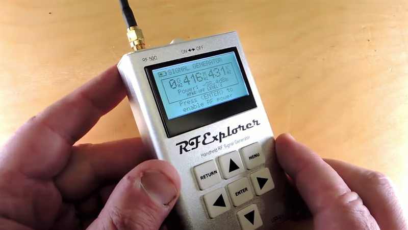
We suppose the fail-badge could be pinned on [electronupdate] for this one in a way; after all, he did shell out $200 for the RF Explorer signal generator, which touts coverage from 24 MHz to 6 GHz. But in true lemons-to-lemonade fashion, the video below he provides us with a thorough analysis of the unit’s performance and a teardown of the unit.
The first step is a look at the signal with a spectrum analyzer, which was not encouraging. Were the unit generating a pure sine wave as it should, we wouldn’t see the forest of spikes indicating harmonics across the band. The oscilloscope isn’t much better; the waveform is closer to a square wave than a sine. Under the hood, he found a PIC microcontroller and a MAX2870 frequency synthesizer, but a conspicuous absence of any RF filtering components, which explains how the output got so crusty. Granted, $200 is not a lot to spend compared to what a lab-grade signal generator with such a wide frequency range would cost. And sure, external filters could help. But for $200, it seems reasonable to expect at least some filtering.
We applaud [electronupdate] for taking one for the team here and providing some valuable tips on RF design dos and don’ts. We’re used to seeing him do teardowns of components, like this peek inside surface-mount inductors, but we like thoughtful reviews like this too.


Looks like a DDS chip and some flying leads would be about as effective at a tenth or twentieth the cost.
DDS at 6GHz? (sine?)
“We suppose the fail-badge could be pinned on [electronupdate] for this one in a way; after all, he did shell out $200 for the RF Explorer signal generator,”
I think he redeemed himself quite nicely by making the video and pointing out to the rest of us its shortcomings.
Normally the output of this chip is quite clean (harmonic wise) above 3GHz since it is then no longer using it’s internal divider. Using the divider the output is almost a square wave and full of harmonics. It also generates significant spurs related to the pll but the high pfd frequency puts them quite far beyond the loop bandwidth. In fractional mode there will be more spurs, so the device may be cleaner on frequencies that are a multiple of the reference frequency.
Of course, many a cheap signal generator in the old days were not too clean, and some seemed to rely on harmonics for the highest band(s).
Decades ago in Ham Radio magazine there was an article describing a set of filters from about 25MHz through low microwave, moving from coils to stripline along the way. Build them up as a set, and they can be used for all kinds of things, for testing or tossing together temporary projects.
Michael
Do you have a reference for that? Year, issue number?
My Google-fu is not finding it
I am not sure why this is a fail. Did they lie abut the spurs in devices specs? If that was something the buyer overlooked or bought one without knowing, and it was important to them, than they screwed up not the device. Without showing the full datasheet for the device it is hard for me to call it a fail. From what the dude who made the video said, the box did what it advertised. And as he said, you have to expect some differences between a $200 device and a $2000 device.
You have to judge a device on how well it meets it’s specs, not how well it works for some random use.
To be fair, they don’t have *any* spur specs for the device, but… that should kinda give you a clue.
Yeah, I’m not sure I’d characterize this as a “fail” – it’s just apparently not what he was expecting. It’s a PLL signal generator. At low frequencies they’ve got tons of spurs – this isn’t unique to this device, you see it all over the place, and the spurs are 10 dB down, which is fairly typical. (See here for another device with extremely similar output harmonics).
It should clean up at the higher frequencies, but who knows how much. Again, for $200, I really wouldn’t consider that a “fail” – there are plenty of uses where it’s fine. You can still use it as a tracking generator no problem.
This is meant to be more for field gear than bench or lab gear, sometimes good enough is all you need…
I hear a lot of emphasis on spurs, and I see a lot of harmonic content, but I don’t see spurs on the spectrum analyzer. “Spurs” means spurious signals, not harmonic content. These are two separate things.
Good point, the two are not interchangeable. I stand corrected. I still however stand by this device not being a fail though.
Adding filter to device like this is big effort, it must be switched or tuned because output frequency is adjustable and ultra high bandwidth.
$200 for handheld sig gen… hmmm. I have $50 chinese LF to 50 function gen that works quite well but still always filter output, no specan to measure spurs but FFT gave me well enough idea and was much cleaner than older discrete solid state siggens from hamfests… hafta dig through notebooks if anyone wants numbers.. maybe will make blog post..
the portabality aspect of the device. What are realistic use scenarios? What is the benefit from the handheld form ?
I would expect a lot more for $200 today but I suppose if it has a good frequency range it may be worth it.. simple 50ohm circuits on output will create harmonics as high as your want and filters are easy to whip up from scratch usin what u got. lots of software out there for filter design.
just showin my drunkin homebrewing thoughts. Love RF posts here.
stay fluxy friends.
“Granted, $200 is not a lot to spend compared to what a lab-grade signal generator with such a wide frequency range would cost.”
Maybe so but that is still a lot of money to spend on a square wave. At $200 I would expect something in between lab-grade and junk, not just junk. I would be pissed!
I have one and it works fine. Their QA/QC is straight up nonexistent, the case is flimsy and looks like its meant for prototyping, the screen is a cheap POS, and the firmware is hot garbage. Oh, and the screen printed logos on the front will flake off after 6 months. Its not meant to compete with a benchtop siggen, its more of babies-first-portable siggen for a classroom environment (like where I use it).
Its also great if you hook it up to a 2.4ghz amp and a directional antenna. It can put enough noise in the environment to make deauths run a bit smoother. :3
Spend big money, get good tools. Spend a few bux on garbage on amazon, dont be surprised when you get harbor freight tier tools.
I was thinking of buying one of these. I don’t need 6GHz [5GHz is good, 3GHz will do] but I’d like to get down under 10MHz at the bottom end [and 455KHz would be even better].
The lack of bottom end range already had me holding back, this review confirms I was right to hesitate.
Any suggestions on what WOULD be a better signal source? In a similar price range?
You are asking for a clean output over a 10,000 to 1 frequency range in a small handheld instrument for $200. Just the filters, relays, and shielding will take up space.
Are you looking to align AM and FM radio IF sections with 455kHz and 10.7MHz? I think I’d go with a dedicated sig gen for that.
Hiya
The morpheus signal generator covers 85MHz – 5400GHz, is the same price ($199) and gives out a very clean signal. I can also be used as a LO and Mixer module for 30MHz – 6GHz.
https://othernet.is/products/morfeus-1
Cheers
Hiya
PTS frequency synthesizers can be got from the usual auction sites for about the same price e.g. PTS 160 0.1-160MHz . They can be locked to an external standard and were used for filter and coil characterisation for early NMR systems so give a clean output.
You could also just use a DDS signal generator to 4400MHz controlled by an arduino as a project for under $50.
Cheers
Thanks for the video and comments.
Unfortunately the video does not cover important functionality offered by the device, such as its great frequency and amplitude stability, demanded by many users as the main requirement. No one from this produced video contacted the designers to clarify any question or concern.
While harmonics are a known limitation of the device (and published in the specifications at http://rf-explorer.com/RFE6GEN), they come from the MAX2870 PLL. There are plenty of applications where harmonics are not an issue or, in fact, are useful. As an example, Harmonics are not a limiting factor for Tracking Generator applications – see how this works at http://j3.rf-explorer.com/43-rfe/how-to/145-how-to-sna-measuring-rf-filter-response-step-by-step.
Some advanced users who work at 6-12GHz range make a good use of the second harmonic as well.
In fact, this low cost RF Signal Generator, as many other low cost options available, may require external filtering for certain applications, which is easy to do for a specific frequency. For ISM/GSM/WIFI and other popular frequencies, there are SMA shape low cost low pass filters widely available in the market. That is totally different cost to produce an internal, wideband high attenuation filter. We are working to produce an expansion board to enable harmonic filtering with a sophisticated filter switch bank and fine granular power selection with 0.25dB resolution. As this will come as an expansion (optional) board, customers can select whether they need to pay for the extra features.
Designing a fully factory calibrated, highly frequency stable device for $189 is a challenge. The fact is there is no other standalone certified device at this price in the market. On top of the BOM cost, you need to add production cost (we all want fairly paid workers, right?), certification lab cost (including EMC, CE, MSDS), as well as QA labor hour for calibrating the 8*160 datapoints using a expensive Keysight CXA N9000B, which cost >$25,000 plus $1,500 every year to recalibrate. Then you can realize the distributor takes their own margin as well.
Not to mention development of free open source python and .net libraries, or regular firmware upgrades at no cost, support, warranty.
As a comparison, the MAX2870 evaluation board from Maxim is listed at $319, being a certified but uncalibrated board, with no screen, keyboard or case.
Regarding the PCB design exposed in the video, it is designed carefully to offer low intermodulation of digital signals in the RF signal path, as well as low impedance GND return path. Digital signals traces should be carried parallel only if are part of a differential bus, or if the resulting radiation is in no risk of mixing into a RF signal. Bad things happens if you keep high speed digital signal traces without GND band guard among them, relatively close to a sensitive RF path.
A lot of good points.
Just in case you didn’t know, RF Explorer released an improved version – RF Explorer Signal Generator Combo: http://j3.rf-explorer.com/menu-the-news/212-introducing-new-rf-explorer-signal-generator-combo
Has anyone heard of Vaunix and their line of Lab Brick portable RF Test Devices and done a similar evaluation?
You can buy pretty much this exact thing, but in a different layout and with no case, if you search MAX2870 on ebay. And they’re like 1/5 the price of this