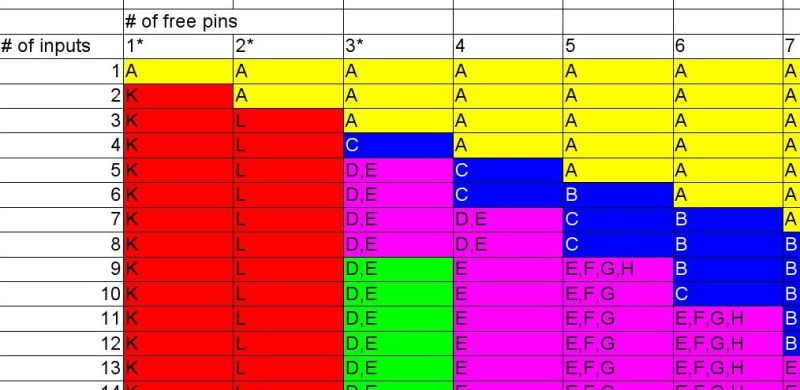
 So you’re building a new mechanical keyboard. Or attaching a few buttons to a Raspberry Pi. Or making the biggest MIDI grid controller the world has ever know. Great! The first and most important engineering question is; how do you read all those buttons? A few buttons on a ‘Pi can probably be directly connected, one for one, to GPIO pins. A mechanical keyboard is going to require a few more pins and probably some sort of matrix scanner. But the grid controller is less clear. Maybe external I/O expanders or a even bigger matrix? Does it still need diodes at each button? To help answer these questions the folks at [openmusiclabs] generated a frankly astounding map which shows, given the number of inputs to scan and pins available, which topology makes sense and roughly how much might it cost. And to top it off they link into very readable descriptions of how each might be accomplished. The data may have been gathered in 2011 but none of the fundamentals here have changed.
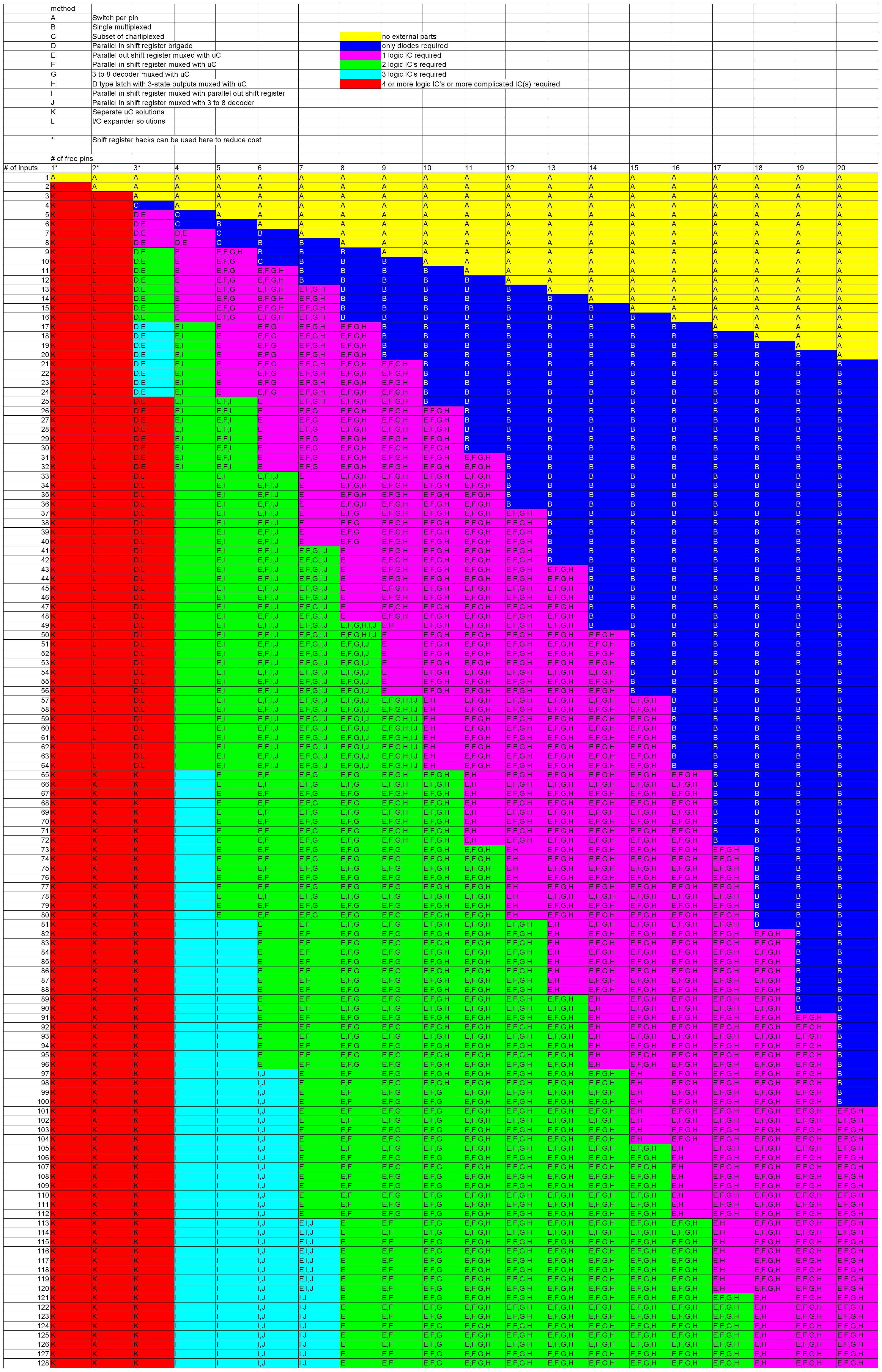
How do you read this chart? The X axis is the number of free pins on your controller and the Y is the number of I/Os to scan. So looking at the yellow band across the top, if you need to scan one input it always makes the most sense to directly use a single pin (pretty intuitive, right?). Scrolling down, if you need to read 110 inputs but the micro only has eight pins free there are a couple choices, keys E and F. Checking the legend at the top E is “Parallel out shift register muxed with uC” and F is “Parallel in shift register muxed with uC“. What do those mean? Checking the table in the original post or following the link takes us to a handy descriptive page. It looks like a “parallel out shift register” refers to using a shift register to drive one side of the scan matrix, and “parallel in shift register” refers to the opposite.
While we’re here, we think it’s worth reproducing the footnote at the bottom of the post in full:
This tutorial was motivated by the fact, that when we put our engineering caps on, we often end up re-inventing the wheel. And although this can be amazingly fun and rewarding, at some point it really hinders the forward progress of our projects, and the state of the art in general. So the more we can document those things we’ve learned while solving our own little problems, the less someone else will have to do the same thing, and the more cool things there will be in the world.
An eloquent way to phrase why we enjoy writing Hackaday so much. Keep up the awesome projects!


Some interesting methods there!
But there’s one very practical way to increase the number of usable switches without using external ICs that it is missing: use an MCU with more pins.
Hence the horizontal axis on that table.
Yeah, but it only goes to 20, which gives a maximum of 100 switches without additional ICs. Which is probably not enough on a table that goes up to 128 switches. I’m in the process of building a mechanical keyboard, and have 21 IOs for the switch matrix, two more for a TrackPoint, and three for LEDs, in addition to two for USB and two for SWD. I’ve also got four IOs left over that I haven’t used. And that’s just a cheap generic STM32F103 board from China (“Blue Pill”).
And besides, to me it seems the point of the table is to suggest how to do something with a particular number of IOs.
It’s option K on the chart, essentially the most expensive.
I read option K as being to add another MCU for the express purpose of reading switches. That would be expensive. But changing to an MCU with a few more pins (e.g. 48 pin instead of 32) would probably be cheaper than adding a shift register.
Option K is listed as ‘add an extra uC’ but in the description text, it does suggest “if your main microcontroller is running out of pins to scan a matrix, it’s probably cheaper to get a larger device than add another one.”
However, having been in a similar situation myself, I went down the extra uC route because it ticked quite a few boxes, not least because it was the cheapest option.
There’s board space (easier to fit in two small uC vs single large one), quantity discounting (using the same uC elsewhere) and it was still cheaper than buying a dedicated I/O expander chip while also offering more control mediums (PWM outputs, analogue inputs)
Or use a cheap CPLD like a iCE40HX1K in a 144 pin package. That will give you 90+ more pins and enough left over for a SPI or I2C slave interface – even a cascadable one.
Guarantee you can get a SPI-using I/O expander with 90-ish I/O for cheaper than that 144-pin FPGA.
Not on Mouser at least. A 60 I/O expander is more expensive than the iCE40 chip, didn’t see a 90 I/O expander.
Mouser sells iCE40HX1K-TQ144 at $5.10/@1 ; $4.00/@100. 144 pin TQFP, 0.5mm pitch, 97 I/O
Mouser sells ATSAMC20N17 at $2.78/@1 ; $2.29/@1000. 100 TQFP, 0.5mm pitch, 84 I/O, AND you only need one power supply not two.
(Mouser sells iCE40HX1K-VQ100 at $4.45/@1 ; $3.50/@100. 100 TQFP, 0.5mm pitch, 72 I/O)
Yes, 84 is not 97, but it’s also half the price, and you still have to program both.
Multiple ICs are probably still more affordable. The iCE40HX1K-TQ144 is 4.2¢ per pin ; the ATSAMC20N is 2.7¢ per pin ; a brigade of 74HC165D652 is 1.375¢ per pin in qty 1000.
Any thoughts to using a modified DTMF-like scheme to improve the range?
I have recently added a TCA8418 to a project and it works great.
It also handles debouncing internally and has an INT pin to signal a microcontroller.
There’s an Arduino library which only works with AVR but an update is in the works.
I hacked it slightly to remove some references to AVR specific timers and use it in poll configuration.
http://www.ti.com/lit/ds/symlink/tca8418.pdf
I’m in the process of designing something with one too! Post a reply or something if you find the updated lib
TM1637 can drive six 8 segment led displays and scan 16 button keypad thru I2C in a 20 pin package.
one of craziest solutions i have ever seen was to use r2r ladder, having ic with 8ch 16bit adc you can handle 128 buttons with only resistors required
You’re probably not going to get the full 16 bits out, but you’ll absolutely get a small handful in over a single ADC pin.
I was shocked (shocked!) to see this gimmick used live in a cheap video microscope control panel. https://hackaday.com/2017/06/26/hacking-an-inspection-microscope/
(BTW: I say it in the writeup, but the mount on that thing is soo wobbly that you really shouldn’t buy one unless you’ve got plans to build it a proper stand.)
Just because it is a “16-bit” ADC does not mean that it is perfectly DC accurate to 1/2 MSB withotu calibration. You’ll need guard bands for 5% resistor dividers with limited E24 values. The practical limit is more like 5 or 6 bits out of it.
FYI: It is used on a lot of electronics to save on pin count. e.g. LCD monitor driver boards, TV and even those $2 MP3 player. The added advantage is that a single cap can be used to reduce EMI and/or debounce those switches.
Some headsets with buttons on the audio cable to that with a few buttons. I used that trick too, up to 5 buttons. It worked well but require to filter the input to be certain to detect a stable voltage instead of a raising or falling edge. This put a unavoidable limit to the smallest detectable pulse and to the minimal latency.
Also was used for ages in automotive applications, particularly steering wheel buttons, as a cheap “1 wire” interface.
That’s not THAT crazy. Making an RF circuit to do it, maybe. Like measuring resonance frequency, or signal reflection time. Black magic.
“Ya wanna hear a scary story, kids? In this very forest of PCBs, there is a series of buttons daisy-chained one to another. One hundred and twenty seven buttons. If you push any of them, a seven-segment display shows the number of that button. Always accurately. That display is connected to an Arduino. So is the chain of the buttons. But only one end of it, because the other end is connected to… NOTHING!”
Truly, the stuff of nightmares
Why not a “use a keyboard encoder chip” option? Choose one that can recognize as many inputs simultaneously closed as will meet or exceed your design’s maximum inputs simultaneously closed.
They forgot the simple method of using buttons to short out taps on a voltage divider, and using a AD pin to read that voltage. I have successfully read in 6 different buttons using one analog input pin.
They forgot a very simple configuration which I’ve seen on cheap remote controls. Pin 1 connects through switches to pins 2..N, pin 2 connects through switches to pins 3..N, pin 3 to pins 4..N, etc. So for 7 pins, you get 21 switches, for 5 pins, you get 10 switches, etc.
Isn’t that just half of their charliplexed suggestion?
You would think so, but the number of buttons is too small. e.g. for 5 pins, they say 8 inputs, but you can get 10 as I described, for 6 pins, they say 10, but I say 14, and they don’t list for any greater pin count. The method must be different.
all the handwired keyboards use a rectangular array eg 6*18 which makes routing easy but is wasteful of pins. a square array or almost square of 11×11 or 11×10 is more than enough for even a full size backlit keyboard with modifier indicator leds.
Gotta go careful if it’s actually something you wanna type on though. Have to make sure your modifier keys can be read alongside normal keys or you will get spurious output. Then keys that might be often used in combination like T and H might get pressed milliseconds apart by a fast typist and cause a row/column combo that’s interpreted as an E maybe instead of T and H
well I understand a diode per switch is standard in most builds to prevent spurious output. although extending the routing wires may cause a switch delay the difference would be on the order of nanoseconds due to the speed of electricity being close to the speed of light. man can just about measure milliseconds but microseconds and nanoseconds are a different story.
When I need more io buttons, I sometimes share buttons with leds using a resistor, some code to make sure the led doesn’t light when the button is pushed.
1) sad the analog ADC trick wasnt included but maybe author confused uC with standard logic. then again title of article is “SCAN” buttons…
2) it is correct to state that the analog trick can only go so far, max buttons determined by ADC error and resistor tolerance.
3) but for crying out loud; people talking about 5+ ways of multiplexing digital signals should be able to multiplex multiple analog signals onto one ADC input. You might be thinking about 4016 or 4066 (ect) but simpler is use transistors to multiplex power connection of each set of switch-resistors. use transistor to build reset circuit that activates reset of counter when INVALID switch voltage present. supply this invalid (~5v) FROM uC-pin by switching it from ADC(input) to output(logic-HIGH) then (after switching GPIO back) measure voltage from 1st set of resistors, pulse clock line to advance then measure ADC for next set of buttons. USES TWO WIRES and with today’s built-in ADC’s your looking at over 144 different buttons with two wires. not bad for not needing huge I2C or SPI library! (or whatever chip is “in style”). with an extra ADC input you double it to 288 buttons… (same 4040 different sets)
edit: only counts of powers of two work, so reset AND clock/count THEN read 1st set…
edit: USE A COUNTER WITH 12 OUTPUTS, such as a 4040
standing on the shoulders of giants (Latin: nanos gigantum humeris insidentes) expresses the meaning of “discovering truth by building on previous discoveries”
I love it all, thank You community!!!
I’m into this. I’m thinking I might design a few mini keyboards with those little square clicky buttons using these methods. Cool article, thanks.